

M
Mike RamseyAug 8, 2025
What to do if Daikin FCQG35FVEB Air Conditioner detects multiple master units?
- Kkatie46Aug 8, 2025
If your Daikin Air Conditioner detects multiple master units, connect the remote controller to only one indoor unit.
What to do if Daikin FCQG35FVEB Air Conditioner detects multiple master units?
If your Daikin Air Conditioner detects multiple master units, connect the remote controller to only one indoor unit.
What to do if Daikin FCQG35FVEB has gas shortage due to clogging in refrigerant piping?
If you suspect clogging in the refrigerant piping system of your Daikin Air Conditioner, check for a failure to open the stop valve and any clogging within the refrigerant system.
What does excess indoor units connected error mean on Daikin Air Conditioner?
This error will be displayed if five or more indoor units are connected to your Daikin Air Conditioner.
Why does my Daikin Heat Pump emit an odor?
If your Daikin Heat Pump emits an odor, it's likely due to room smells and cigarette odors that have accumulated inside the indoor unit. To resolve this, the inside of the indoor unit must be cleaned.
Lists functions for cooling-only operation of various indoor and outdoor units.
Lists functions for heat pump operation of various indoor and outdoor units.
Provides detailed technical specifications for outdoor and indoor units in cooling mode.
Provides detailed technical specifications for outdoor and indoor units in heat pump mode.
Details connectors and parts on the main and service monitor PCBs of outdoor units.
Details connectors and parts on the control, signal receiver, display, and sensor PCBs of indoor units.
Lists connectors and parts for wired remote controllers like BRC1D528 and BRC1E52A7/B7.
Explains various control functions for RA indoor units like temperature, airflow, and modes.
Details control functions for SA indoor units, including drain pump and thermistor usage.
Explains the roles of various thermistors in the system for temperature detection and control.
Outlines control specifications, including mode hierarchy, frequency control, and protection functions.
Describes how to handle and operate the air conditioner after installation and trial operation.
Provides manual contents and reference pages for RA indoor units like FTXG, FTXS, CTXS, FVXG, FVXS, FLXS, FDXS series.
Details manual contents and reference pages for SA indoor units like FCQG, FFQ, FHQ, FDBQ, FBQ series.
Explains how to troubleshoot indoor and outdoor units using LED indicators for error detection.
Lists common problem symptoms and their corresponding measures for diagnosing issues.
Provides methods for checking the system's functionality and diagnosing errors using remote controllers.
Lists error codes displayed on the remote controller for RA and SA indoor units and their descriptions.
Offers detailed troubleshooting steps for common abnormalities in RA indoor units.
Provides troubleshooting guides for SA indoor units, covering PCB, fan motor, and drain system issues.
Lists common troubleshooting steps for outdoor units, including refrigerant shortage and PCB abnormalities.
Details various checks for components like thermistors, fan motors, Hall IC, and electronic expansion valves.
Provides step-by-step instructions for removing outer panels, electrical box, PCBs, fan, and compressor.
Details the procedure for removing outer panels, electrical box, PCBs, fan motor, and compressor for 80/90 class outdoor units.
Explains the procedure for pump down operation when relocating or disposing of the unit.
Describes how to select and start forced cooling or heating operation modes.
Details the wiring error check function and its usage for diagnosing connection issues.
Outlines the steps for performing trial operation and checking functions, including remote controller usage.
Explains how to perform field settings, including outdoor unit and indoor unit configurations.
Provides piping diagrams for outdoor and indoor units, showing refrigerant flow and connections.
Includes wiring diagrams for outdoor and indoor units, detailing component connections and PCB layouts.
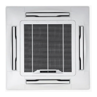
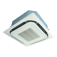
| Type | Ceiling Cassette |
|---|---|
| Cooling Capacity | 3.5 kW |
| Heating Capacity | 4.0 kW |
| Energy Efficiency Ratio (EER) | 3.21 |
| Noise Level (Outdoor Unit) | 48 dBA |
| Refrigerant | R32 |
| Outdoor Unit Dimensions (WxHxD) | 765x550x285 mm |
| Outdoor Unit Weight | 34 kg |
| Cooling Capacity (Btu/h) | 11900 BTU/h |
| Heating Capacity (Btu/h) | 13600 BTU/h |
| Energy Efficiency Ratio (Cooling) | 3.21 |
| Power Supply | 220-240V |
| Dimensions (Indoor Unit) | 840x204x840 mm |
| Indoor Unit Dimensions (WxHxD) | 798 x 295 x 223 mm |
| Weight (Indoor Unit) | 9.5 kg |
| Indoor Unit Weight | 9.5 kg |