J
jasmine99Aug 9, 2025
What to do if Daikin FCQG71FVEB detects multiple master units?
- DDominique PageAug 9, 2025
If your Daikin Air Conditioner detects multiple master units, connect the remote controller to only one indoor unit.
What to do if Daikin FCQG71FVEB detects multiple master units?
If your Daikin Air Conditioner detects multiple master units, connect the remote controller to only one indoor unit.
What to do if Daikin FCQG71FVEB has gas shortage due to clogging in refrigerant piping?
If you suspect clogging in the refrigerant piping system of your Daikin Air Conditioner, check for a failure to open the stop valve and any clogging within the refrigerant system.
What does excess indoor units connected error mean on Daikin FCQG71FVEB Air Conditioner?
This error will be displayed if five or more indoor units are connected to your Daikin Air Conditioner.
Why does my Daikin Heat Pump emit an odor?
If your Daikin Heat Pump emits an odor, it's likely due to room smells and cigarette odors that have accumulated inside the indoor unit. To resolve this, the inside of the indoor unit must be cleaned.
Records changes and updates to the service manual over time.
Essential safety guidelines to follow before and during repair work.
Explains the meaning of various icons used in the manual for clarity.
A brief introduction and thank you note from the manufacturer.
Lists and categorizes the various indoor and outdoor unit model names.
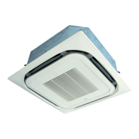
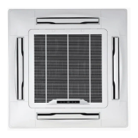
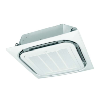
Provides visual representations of the different outdoor unit models.
Details the operational temperature and humidity limits for different unit types.
Covers applicable models, names, and functions of wired remote controllers.
Details applicable models, names, and functions of wireless remote controllers.
Procedures for entering and using service modes for remote controller diagnostics.
Steps for performing inspection mode on different remote controller models.
Explains the roles of key components and thermistors in the system.
Visual representation of the cooling/dry and heating operation processes.
Detailed explanations of various indoor and outdoor unit functions.
Guidelines and steps for performing a test operation after installation.
Procedures for configuring unit settings using wired and wireless remote controllers.
Instructions for setting parameters using DIP switches and BS buttons on the outdoor unit PCB.
Methods for operating the unit in emergency situations or when the remote controller is lost.
Outlines essential inspections to perform during routine maintenance.
Guides users through troubleshooting based on observed symptoms.
Diagnosing issues by interpreting LED indicators on indoor and outdoor unit PCBs.
Procedures for diagnosing errors and warnings displayed on the remote controller.
Visual diagrams illustrating the refrigerant piping layout.
Electrical wiring diagrams for the outdoor unit.
Technical data on the thermodynamic properties of the refrigerant.
Step-by-step instructions for removing and mounting the switchbox.
| Model | FCQG71FVEB |
|---|---|
| Category | Air Conditioner |
| Brand | Daikin |
| Type | Ceiling Cassette |
| Cooling Capacity | 7.1 kW |
| Heating Capacity | 8.0 kW |
| Energy Efficiency Ratio (EER) | 3.21 |
| Indoor Unit Dimensions (W x D x H) | 840 x 840 x 204 mm |
| Indoor Unit Dimensions (HxWxD) | 204 x 840 x 840 mm |
| Power Supply | 220-240V, 50Hz |
| Power Source | 220-240V, 50Hz |