Removal of Air Filters / Front Panel Si041055
4 Removal Procedure
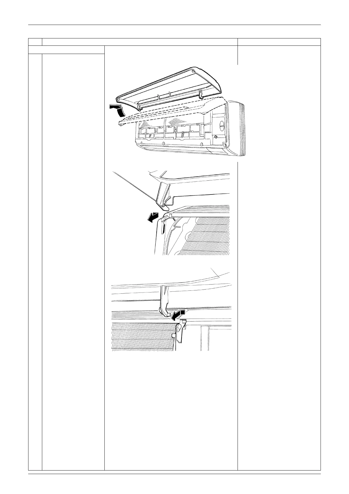
4. Remove the front panel.
1
While opening the front
panel further than it
stops, release both the
shafts and remove the
front panel.
Slide the front panel from
side to side to release each
shaft.
When reassembling the front
panel, fit the right and left
rotary shafts one by one into
the grooves and fully push
them into position.
Step Procedure Points
(R2753)
(R2754)
(R2755)