PCBs Si041251EC
12 Removal Procedure
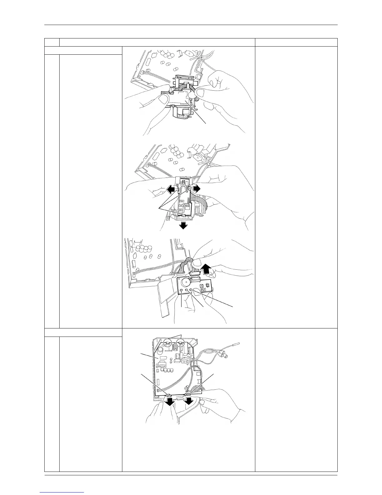
7. Remove the display PCB.
1
The display PCB is
located at the back of
the signal receiver unit.
2
Unfasten the 3 hooks
and remove the display
PCB.
3
Disconnect the
connector [S27] from
the display PCB.
8. Remove the control PCB.
When reassembling the
control PCB, make sure that
it is fastened by 2 upper
hooks.
1
2
Unfasten the 2 lower
hooks.
Lift up the bottom of the
control PCB and pull it
out.
Step Procedure Points
Display PCB
(R4366)
(R4367)
Hook
Green
LED 1
Green
LED 3
Yellow
LED 2
(R4368)
[S27]
Control
PCB
Hook
Hook
Hook
(R20214)
 Loading...