Outdoor Unit SiENBE12-713
292 Removal Procedure
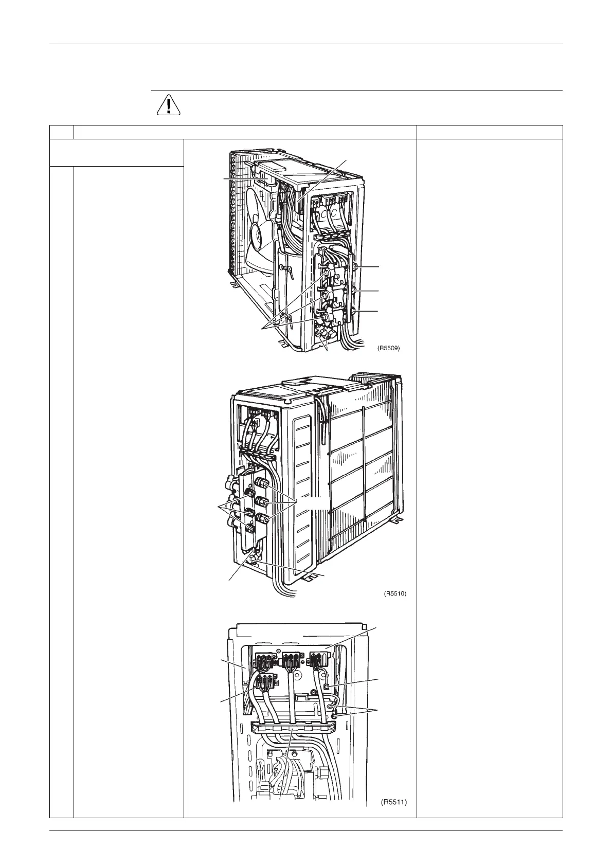
1.2 Removal of the Electrical Box
Procedure Warning Be sure to wait 10 minutes or more after turning off all power supplies
before disassembling work.
Step
Procedure Points
1. Disconnect the
connecting wires
' Illustrations are for 3 room
model. (4MK(X)S-F models
have 4 ports)
1
Inside structure.
2
Disconnect the
connecting wires.
" Connecting wires of the A, B,
C, D port
(1) - Black Power supply
(2) - White Power supply
(3) - Red Transmission
" Power Supply wires
(L) - Black
(N) - White
" Fasten the wires on the
terminal board with screws.
Services PCB
Electronic expansion
valve coil
Service port
A port
C port
B port
Electrical
box
Liquid
pipe
Liquid stop valve
Gas stop valve
Gas pipe
Service
PCB
C port
A port
B port
Earth
Earth
wires
Power
supply
terminal
board
Wiring fixfure
 Loading...
