English
1-7
MAIN SUPPLY
OVER FLOW PIPE TO NEAREST DRAIN / FLOOR TRAP
MAKE-UP
WATER TANK
CHILLED WATER SUPPLY
CHILLED WATER RETURN
PRESSURE GAUGE
THERMOMETER
BALL VALVE
GATE VALVE
MINI AIR
COOLED
CHILLER
GLOVE VALVE
FLEXIBLE JOINT
CHECK VALVE
STRAINER
CEILING
CEILING
CEILING
CEILING
CEILING
RC SLAB
RC SLAB
RC SLAB
RC SLAB
FCU 1
DUCTING
AIR VENT
STRAINER
BALL VALVE
GATE VALVE
3 WAY VALVE WITH
THERMOSTAT
FLEXIBLE HOSE
DRAIN PIPE TO NEAREST DRAIN / FLOOR TRAP
RC SLAB
TM
FCU 2
FCU 3
FCU 4
T
M
T
M
T
M
FCU 5
T
M
P
T
P
T
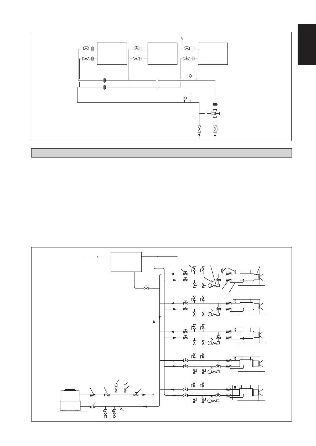
Schematic Diagram For Mini Air Cooled Chiller Installation
GUIDELINES FOR VALVE AND FITTING INSTALLATION
Gate valves (shut-off) are installed in the entering and
leaving piping to the chiller and fan coil unit. This is to
permit servicing and replacement of the equipment without
draining the system. A globe valve may be used to serve
as one of the shut-off valve and in addition to balance the
rate.
Valves and fittings using threaded or welded joints will
require unions to permit easy removal for servicing or
replacement. Unions are usually located between each
gate valve and the equipment. Unions are also place before
and after the control valve, and in the branch of the 3-way
valve.
If flange joints are used, the need for unions is eliminated.
a.
b.
Locate the control valve in between the gate valve and the
equipment to permit removal of the control valve without
draining the system.
Strainers, thermometers and pressure gauges are located
between the gate valve and the equipment.
The following diagrams illustrate examples of piping
layout:
c.
d.
T
T
FCU 1 FCU 2 FCU 3
GLOBE
VA LV E
AIR VENT
3-WAY
DIVERTING
VA LV E
** All three fan coil units to serve one area with a common
thermostat. When temperature has reached set point, thermostat
will send signal to 3-way valve to divert water away.
Multiple fan coil unit installation
1 IM-SBBW-0314(1)DAIKIN-EN.indd 71 IM-SBBW-0314(1)DAIKIN-EN.indd 7 1/9/15 9:38:54 AM1/9/15 9:38:54 AM
 Loading...