15 | Piping installation
Installer and user reference guide
97
LREN8~12A7 + LRNUN5A7
CO₂ ZEAS outdoor unit and capacity up unit
4P704142-1 – 2022.08
15.4.1 About checking the refrigerant piping
15.4.2 Checking refrigerant piping: General guidelines
Connect the vacuum pump through a manifold to the service port of all stop valves
to increase efficiency (refer to "15.4.3Checking refrigerant piping: Setup"[497]).
NOTICE
Use a 2-stage vacuum pump with a non-return valve or a solenoid valve that can
evacuate to a gauge pressure of –100.7kPa (−1.007bar).
NOTICE
Make sure the pump oil does not flow oppositely into the system while the pump is
not working.
NOTICE
Do NOT purge the air with refrigerants. Use a vacuum pump to evacuate the
installation.
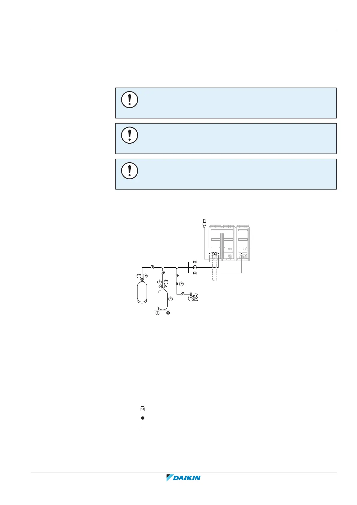
15.4.3 Checking refrigerant piping: Setup
E
a
N2
R744
a
b
b
C
A
B
D
ch i d e
g
b
f
A Nitrogen (N
2
)
B R744 refrigerant tank
C Weighing scales
D Vacuum pump
E Outdoor unit
a Pressure regulator
b Charge hose
c Service port SP3 (gas side)
d Service port SP7 (liquid side)
e Service port SP11 (gas side)
f To refrigeration indoor unit
g Safety valve
h Stop valve (gas side)
i Stop valve (liquid side)
Stop valve
Service port
Field piping
 Loading...


