IM 1005-3 • MICROTECH III REMOTE USER INTERFACE 8 www.DaikinApplied.com
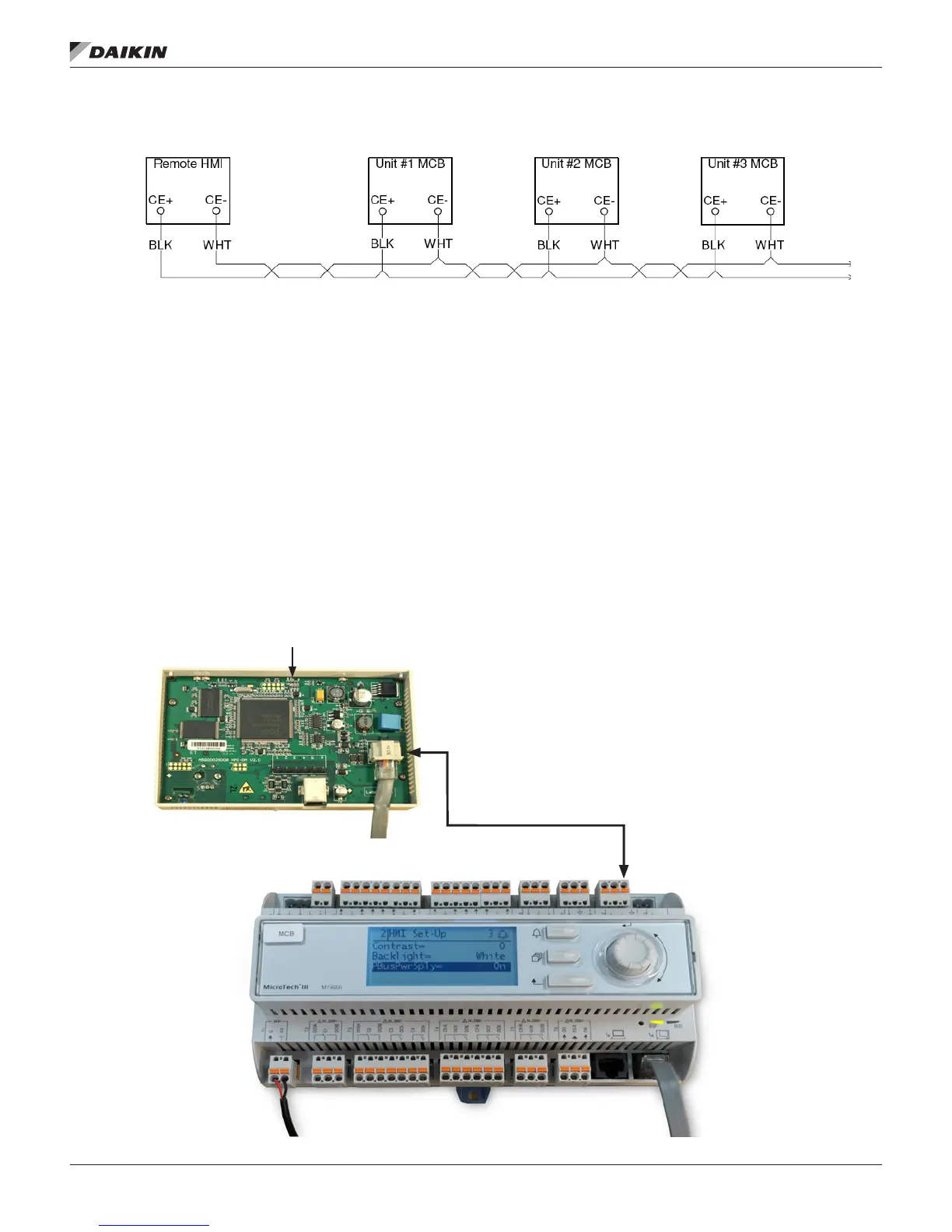
Figure 5: Daisy-Chain Connection Wiring Details
Direct Connection
The remote user interface can be wired directly to a single
MicroTech III unit controller over a standard RJ45 (Ethernet)
connection.
Procedure
1. Locate the connector location as shown in Figure 6
2. Follow Figure 6 for connection details. Note the distance
limitations provided.
3. Cycle power to the unit(s) once the wiring of the remote
user interface is complete.
NOTE: Power is supplied by the unit controller. If a separate
24V power supply is desired, please contact either
the Daikin Applied Air Technical Response Center
at 844-521-3928 (techresponseaah@daikinapplied.
com) or the Chiller Technical Response Center at
540-248-9239 (techresponse@daikinapplied.com).
Figure 6: Interface Details for RJ45 Connector
Bus connection
Max length of shielded cable
Max. length of unshielded cable
Cable type
RJ45 interface
164 ft (50 m)
9.8 ft (3 m)
Standard Ethernet cable
Remote User Interface
Interior Top View