ED 15103-6 • MICROTECH III WSHP UNIT CONTROLLER 20 www.DaikinApplied.com
ComprehensIve daTa Tables
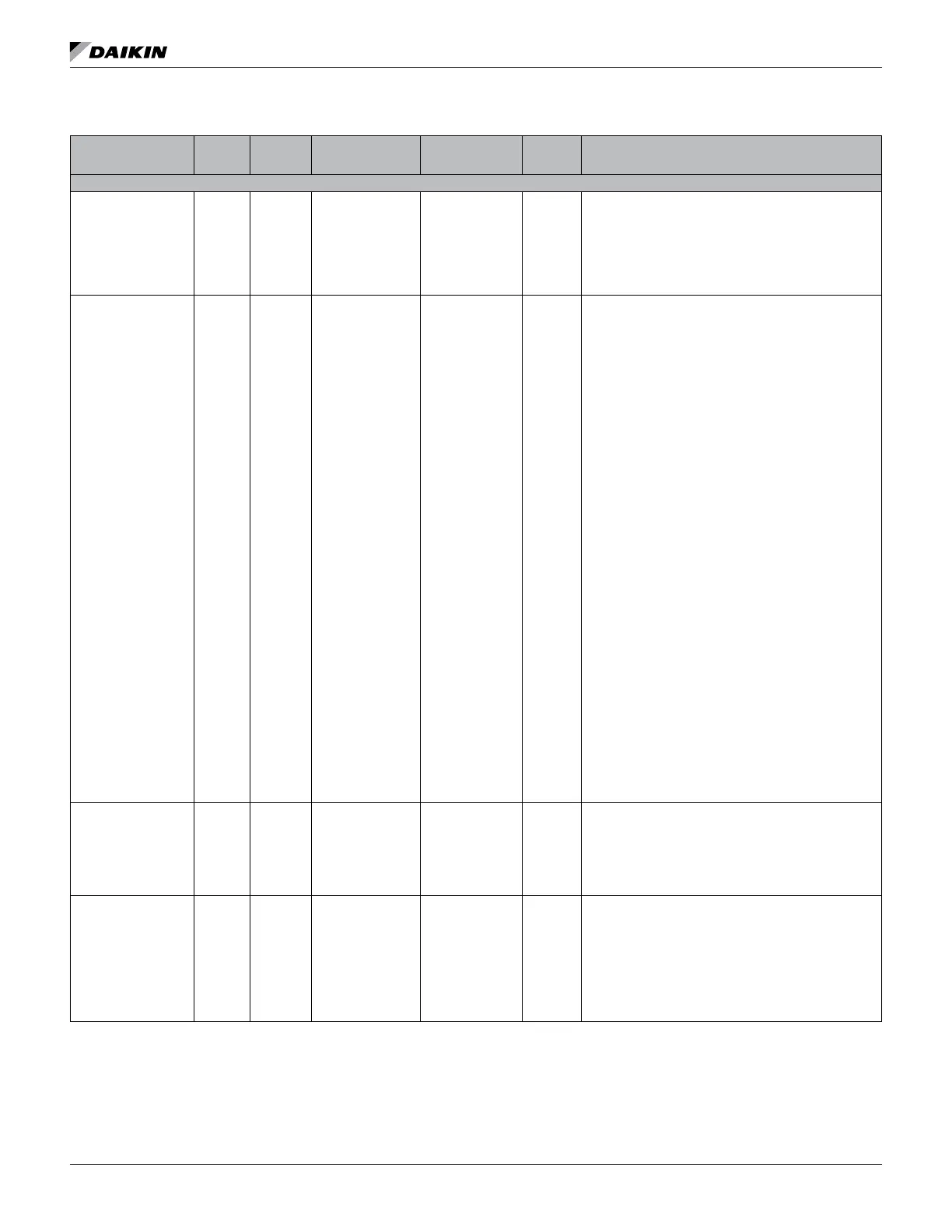
Table 13: Multi-State Values - SmartSource Single and Two Stage, Ennity Large Two Compressor
Point Name
Object
Type/
Instance
Read/
Write
Access
2
BACnet Object
Name
Range/Default
(in Units)
Non-
volatile
Memory
1
Description
MULTI-STATE VALUES
Compressor Enable
Input
MSV:1 C ComprEnable
1 to 3
Default: 3
N
Species if the compressor(s) are allowed to operate, which
can be based on proof of loop uid ow. The loop pump
must be running to provide adequate ow through the unit
so the compressor(s) can operate safely. The network
override will revert back to its default value upon unit
controller reboot.
1 = Disabled
2 = Enabled
3 = Null (compressors are enabled)
Current Alarm MSV:2 R CurrentAlarm
SmartSource
(Series2)
1 to 16
Ennity Large
Two Compressor
(SS2C)
1 to 20
N
Displays the current highest priority active alarm
SmartSource (Series2) Alarms
1 = No Alarms
2 = IO Exp Communication Fail
3 = Invalid Conguration
4 = Low Voltage Brownout
5 = Comp High Pressure
6 = Comp Low Pressure
7 = Comp Suction Temp Snsr Fail
8 = Comp Low Suction Temp
9 = Freeze Fault Detect
10 = Room Temp Sensor Fail
11 = Enter Water Temp Snsr Fail
12 = Leaving Water Temp Snsr Fail
13 = Condensate Overow
14 = Low Entering Water Temp
15 = Serial EEPROM Corrupted
16 = Wtrside Econ Low Temp Cutout
Ennity Large Two Compressor (SS2C) Alarms
1 = No Alarms
2 = IO Exp Communication Fail
3 = Invalid Conguration
4 = Low Voltage Brownout
5 = Comp#1 High Pressure
6 = Comp#2 High Pressure
7 = Comp#1 Low Pressure
8 = Comp#2 Low Pressure
9 = Comp#1 Suctn Temp Snsr Fail
10 = Comp#2 Suctn Temp Snsr Fail
11 = Comp#1 Low Suction Temp
12 = Comp#2 Low Suction Temp
13 = Freeze Fault Detect
14 = Room Temp Sensor Fail
15 = Entering Water Temp Sensor Fail
16 = Leaving Water Temp Snsr Fail
17 = Condensate Overow
18 = Low Entering Water Temp
19 = Serial EEPROM Corrupted
20 = Wtrside Econ Low Temp Cutout
Fan ON/Auto Remote
Input
MSV:3 C RemoteFanOnAuto
1 to 3
Default: 3
N
Overrides the local fan ON/Auto room sensor and
thermostat switch inputs. The local Fan ON/Auto Switch
is only used when MSV:3 is set to 3 (Null). The network
override will revert back to its default value upon unit
controller reboot.
1 = Fan Auto (forces cycling fan)
2 = Fan On (forces fan on)
3 = Null (no override)
McQuay WSHP Status MSV:4 R McQWSHPStatus 1 to 10 N
Indicates the unit’s operating state.
1 = Off Alarm
2 = Off
3 = Start
4 = Fan Only (fan is allowed to operate)
5 = Prepare to Heat
6 = Heating
7 = Prepare to Cool
8 = Cooling
9 = Prepare to Dehumidify
10 = Dehumidication