seleCTed parameTers InformaTIon
www.DaikinApplied.com 47 ED 15103-6 • MICROTECH III WSHP UNIT CONTROLLER
seleCTed parameTers InformaTIon
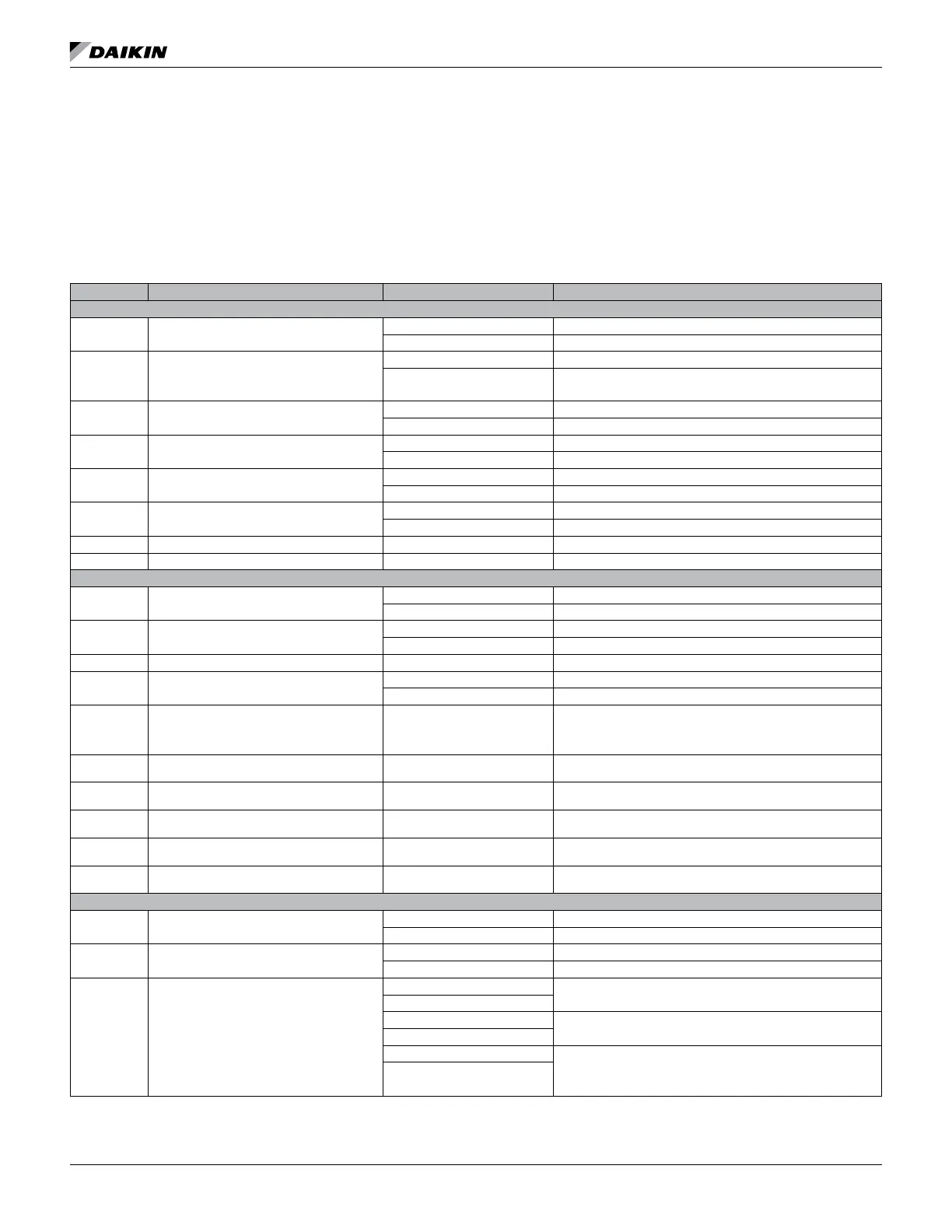
The following section provides greater detail for the Binary
Input Status and Binary Output parameters noted in the
BACnet Network Objects and LonWorks Network Variables
summary tables.
Binary Input Status
Table 21: Binary Input Status Bit Descriptions - Ennity Single Stage Compressor (Models MHC/MHW, CCH/CCW, VFC/
VFW, LVC/LVW, VHC/VHF)
Bit Number Bit Description Setting Description
Unit Controller Jumpers
0 Normal/Test Mode
Jumper 1 = Open (0) Normal operation
Jumper 1 = Shorted (1) Service/Test mode operation
1
Fan Operation
(Jumper applies to unit controller v3.1 and
newer and also for v3.0 and older using room
sensor control without a fan On/Auto switch)
Jumper 2 = Open (0) Continuous fan operation
Jumper 2 = Shorted (1) Cycling fan operation
2 Loop Fluid
Jumper 3 = Open (0) Water loop uid
Jumper 3 = Shorted (1) Glycol loop uid
3
Alarm ‘A’ Terminal Polarity Select
(Unit controller v3.1 and newer)
Jumper 4 = Open (0) Fault de-energizes alarm output to 0VAC
Jumper 4 = Shorted (1) Fault energizes alarm output to 24VAC
4 Room Sensor Setpoint Adjust Range
Jumper 5 = Open (0) Short range: -3º to +3º F (-1.67º to +1.67º C)
Jumper 5 = Shorted (1) Long range: 55º to 95º F (12.78º to 35ºC)
5 Thermostat/Room Sensor
Jumper 6 = Open (0) Thermostat control
Jumper 6 = Shorted (1) Room sensor control
6 Not used Jumper 7 = Open (0)
7 Not used Jumper 8 = Open (0)
Unit Controller Inputs
8 Compressor #1 Low Pressure Switch
Switch Closed (1) Low Pressure Switch for compressor #1 is normal
Switch Open (0) Low Pressure Switch for compressor #1 is in alarm
9 Compressor #1 High Pressure Switch
Switch Closed (1) High Pressure Switch for compressor #1 is normal
Switch Open (0) High Pressure Switch for compressor #1 is in alarm
10 Emergency Shutdown Open (0) Unit shuts down
11 Local Occupancy Switch
Switch Open (0) Unoccupied
1
Switch Closed (1) Occupied
12
Thermostat Timed Override
(O – Terminal)
Switch Closed (1)
If the Timed Override switch is pressed for more than 3 seconds
but less than 10 seconds while in the Unoccupied mode, the
unit goes into the Timed Override mode (the thermostat has a
pushbutton for Timed Override)
13
Thermostat Fan Request
(G – Terminal)
Switch Closed (1) Thermostat fan operation is requested
14
Thermostat Cool Stage #1
(Y1 – Terminal)
Switch Closed (1) First stage of thermostat cooling is requested
15
Thermostat Cool Stage #2
(Y2 – Terminal)
Switch Closed (1) Second stage of thermostat cooling is requested
16
Thermostat Heat Stage #1
(W1 – Terminal)
Switch Closed (1) First stage of thermostat heating is requested
17
Thermostat Heat Stage #2
(W2 – Terminal)
Switch Closed (1) Second stage of thermostat heating is requested
I/O Expansion Module Jumpers
18 Number of Compressors
Jumper 1 = Open (0) Single compressor
Jumper 1 = Shorted (1) Dual compressor
19 Hot Gas/Water Reheat (HGR)
Jumper 2 = Open (0) None
Jumper 2 = Shorted (1) Hot Gas/Water Reheat (HGR)
20 & 21
Secondary Heating Options
(2 Jumpers)
Jumper 3 = Open (0)
None
Jumper 4 = Open (0)
Jumper 3 = Shorted (1)
Supplemental electric heat
Jumper 4 = Open (0)
Jumper 3 = Open (0)
Boilerless electric heat
Jumper 4 = Shorted (1)
1. This switch is effective only when the network scheduling is not in use.