OM 1280-2 • MICROTECH UNIT CONTROLLER 48 www.DaikinApplied.com
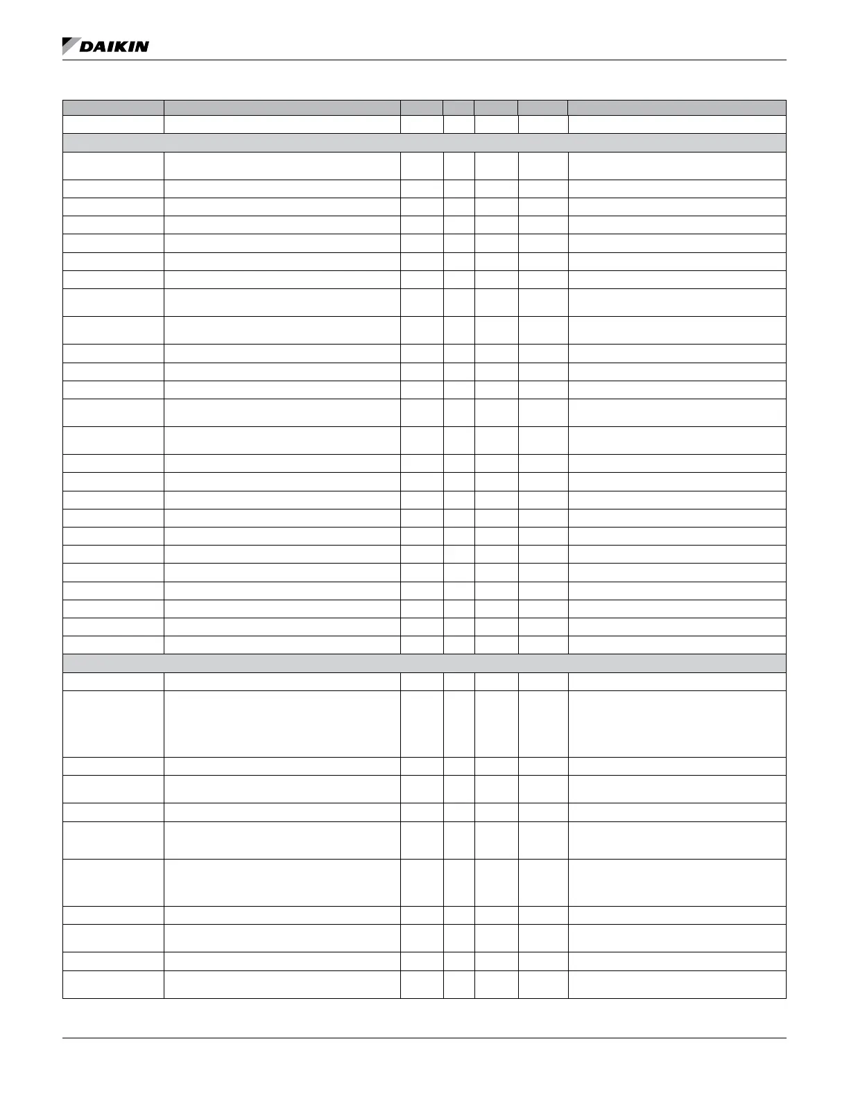
Parameter (LUI) Operating Range (Default) ABV Min Max Default Description
EmergHtSpt 0°F to 70°F EHS 0 70 54 Emergency Heat Setpoint
PI Parameters
FBDPropGn 0.0 to 255.0 0 255 10
Face and Bypass proportional PI loop
FBDIntgGn 0.0 to 255.0 0 255 1
EconPropGn 0.0 to 255.0 0 255 1 Primary cool proportional gain
EconIntgGn 0.0 to 255.0 0 255 0.1 Primary cool integral Time
ClPropGn 0.0 to 255.0 0 255 0.5 Hydro cooling valve proportional gain
ClIntgGn 0.0 to 255.0 0 255 0.02 Hydro cooling valve integral Time
ClMnPos 0% to 100% 0 100 20 Output when temperature delta is zero
ClMxDeltaTmp 1 to 10°F 1 10 5
The delta between control and target
temperatures to cause the valve to open 100%
ClMxPos 10% to 100% 10 100 100
Output when temperature delta is Max Delta
Temp
HtPropGn 0.0 to 255.0 0 255 0.5 Heating Valve Proportional gain
HtIntgGn 0.00 to 255.00 0 255 0.02 Heating Valve Integral Time
HtgMnPos 0% to 50% 0 50 0 Output when temperature delta is zero.
HtMxDeltTmp 1°F to 10°F 1 10 5
The delta between control and target
temperatures to cause the valve to open 100%.
HtMxPos 10% to 100% 10 100 100
Output when temperature delta is Max Delta
Temp.
ElHtPropGn 0.0 to 255.0 0 255 8 Electric heat proportional gain
ElHtIntgGn 0.0 to 255.0 0 255 0.5 Electric heat integral time
CO2PropGn 0.0 to 255.0 0 255 1 OAD control for CO
2
proportional gain
CO2IntgGn 0.0 to 255.0 0 255 0.01 OAD control for CO
2
Integral Time
SZnVAVMxDelta 1°F to 10°F 1 10 5 Used with single zone VAV PI loop
SZnVAVMnFan 0% to 100% 0 100 5 Used with single zone VAV PI loop
SZnVAVMxFan 0% to 100% 0 100 100 Used with single zone VAV PI loop
SZnVAVPropGn 0 to 255 0 255 0.1 Used with single zone VAV PI loop
SZnVAVIntgGn 0 to 255 0 255 0.01 Used with single zone VAV PI loop.
OADLLPropGn 0.0 to 255.0 0 255 2
OADLLIntgGn 0.0 to 255.0 0 255 0.2
Fan
0 sec to 10 sec) 0 10 4
FanCycling 0 1 0
While not in unoccupied mode, this input
determines if the space fan may run
continuously without heating or cooling demand.
Note: nciFanCycling: The fan
cycles when the cp is set to three, and the fan is
continuous when the cp is set to two
PWMLow 50% to 80% 50 80 75
PWMMed 70% to 90% 70 90 90
speed
PWMHigh 80% to 100% 80 100 100
FanRunTm 0.0 hrs to 300,000.0 hrs 0 300,000
This output show the fan run time in hours. It
must have resolution of 0.1 hours and have a
range of at least 300,000 hours
FltrChgHrs 0 to 300,000.0 hours 0 300,000
number of hours that the fan has run with the
memory
BrkptAutoLow 5% to 100% 5 100 5 The percent speed transition point for low fan
BrkptAutoMed 5% to 100% 5 100 75
The percent speed transition point for medium
fan
BrkptAutoHi 5% to 100% 5 100 95 The percent speed transition point for high fan
2% to 20% (2%) 2 20 2
This value is added when going up in speed