This document is an Installation and Maintenance Manual for the Daikin Parallel Fan Powered Variable Air Volume (VAV) Terminal Box, Model MQFV15, identified as IM 1102, dated October 2010. It provides comprehensive instructions for the installation, operation, and maintenance of the unit, along with troubleshooting guidelines.
Function Description:
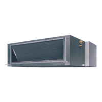
The Daikin Parallel Fan Powered Variable Air Volume (VAV) Terminal Box, Model MQFV15, is an air terminal unit designed to regulate and deliver conditioned air to a space. It incorporates a fan for air circulation and can be equipped with optional electric or hot water coils for heating. The VAV terminal box is a critical component in HVAC systems, providing precise control over airflow and temperature to maintain desired comfort levels within a building zone. It operates by mixing primary conditioned air from the central HVAC system with plenum (return) air, and then discharging this mixture into the occupied space. The "parallel fan powered" design means the fan operates in parallel with the primary air damper, typically running continuously or during heating cycles to induce plenum air and maintain airflow, especially at low primary air flow conditions.
Important Technical Specifications:
- Model: MQFV15
- Manual Identification: IM 1102
- Date: October 2010
- Control Type: Can be equipped with pneumatic, analog, or digital controls. Pneumatic controls require specific orientation (right side up) and level installation (within +/- 10 degrees of horizontal). Most analog and digital controls allow for installation in any orientation.
- Electrical Connection: Factory wired for a single point electrical connection to the fan and optional electric heater. All field wiring must comply with local codes and the National Electrical Code (ANSI/NFPA 70-2002). Copper conductors only are specified.
- Grounding: Must be properly grounded per NEC 424-14 and 250.
- Motor Fusing: Optional unless ordered with electric heaters; required if multiple fan powered units are connected to one branch circuit breaker.
- Ambient Temperature Limits: Not recommended for use in ambient temperatures greater than 95°F for units with controls. Storage temperatures should not exceed 135°F.
- Discharge Static Pressure: Minimum recommended discharge static pressure is 0.2 inches of w.g.
- Minimum Airflow for Heating Coils: 70 CFM/kW across the heating coils to prevent nuisance tripping of reset switches due to high leaving air temperature.
- Flow Sensor: Factory installed pressure differential flow sensor. Calibration data is provided in Figure 4 of the manual, with flow coefficients for various ATU models and inlet sizes.
- Hot Water Coils: Field insulated, do not have a drip pan, and are not suitable for use as cooling coils. Copper tubing should not be used as lift points.
Usage Features:
- Airflow Control: Utilizes a pressure differential flow sensor for accurate airflow measurement and control.
- Heating Capability: Can be ordered with optional electric duct heaters or hot water coils to provide heating to the conditioned space. Electric heaters are balanced by kW per stage, and installers should rotate heater stages by phase for building load balance.
- Access Panels: Designed with two bottom access panels for servicing the motor, blower, actuator, controls, and single point electric power hook-up. These panels should not be obstructed.
- Control Panel Enclosure: Requires a minimum of 18 inches of horizontal clearance for access.
- Start-up/Adjustment: Includes procedures for initial start-up and adjustment of fan flow rate, emphasizing the importance of checking ductwork connections, electrical installations, and inspecting for foreign materials. Speed control adjustment is done by turning counterclockwise to reduce fan speed and clockwise to increase.
- Noise Management: The manual addresses potential noise complaints, distinguishing between discharge noise (caused by high static, internal duct lining, or air outlet) and radiated noise (commonly associated with fan powered units and vibrations). Proper suspension, isolation, and ducting are critical for minimizing radiated noise.
Maintenance Features:
- Motor Lubrication: The motor is equipped with permanently lubricated bearings, reducing the need for regular lubrication.
- Inspection and Cleaning: Regular inspection of the motor, fan, and terminal unit for dust or foreign material buildup is recommended. Cleaning should be performed as required by the operating environment and insulation type.
- Troubleshooting: A dedicated troubleshooting section covers common issues such as motor not running, excessive noise, insufficient airflow, and problems with electric duct heaters.
- Blower/Motor Removal: Detailed steps are provided for removing the blower and motor assembly for repair or replacement, including instructions for disconnecting power, removing access panels, and loosening screws.
- Static Sensitive Components: Cautions against static electricity when working with controls, advising technicians to discharge any static charge by touching bare metal inside the control panel before servicing.
- Safety Disconnects: Optional disconnect switches are available, and a safety disconnect per NEC 424-19, 20 & 21 is recommended.
- Labeling: Units are shipped with various labels providing critical information, including control diagrams, calibration data, tagging information, ARI certification, insulation type, and orientation. These labels are essential for proper installation, operation, and maintenance.