This document is an installation, operation, and maintenance manual for a Daikin Ceiling Concealed Fan Coil Unit, model FWW02-20DA.
Function Description
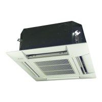
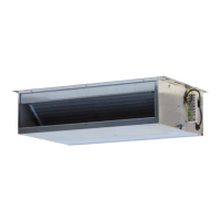
The Daikin FWW02-20DA is a ceiling concealed fan coil unit designed for air conditioning and hot-air heating applications. It is intended for hidden installation within a ceiling space, providing conditioned air through a duct system. The unit is part of a chilled water system, where it circulates water through a coil to either cool or heat the air before it is distributed into the conditioned space.
Important Technical Specifications
Water Circuit:
- Minimum water-side pressure: 0.01 MPa
- Maximum water-side pressure: 1.6 MPa
- Minimum entering water temperature (cooling): 5°C
- Maximum entering water temperature (cooling): 25°C
- Water flow rate: 0.1-2.1 m³/h
- Recommended operation range (cooling): 16-36°C
- Maximum External Static Pressure (ESP): 100 Pa
- Minimum ESP: 40 Pa
Power Supply:
- Nominal single-phase voltage: 220-240V~ / 50 Hz
- Operating voltage limits: ±10% Volt
- Operating frequency limits: ±1 Hz
- Power cord type: H05VV-F
- Wire size: AWG16 (or 1.5mm²)
Water Quality Requirements (Base Value):
- pH value (25°C): 6.5-8.0
- Conductivity (25°C): < 800 µS/cm
- Chloride (CI⁻): < 200 mg(CI)/L
- Sulfate (SO₄²⁻): < 200 mg(SO₄)/L
- Acid consumption (pH=4.8): < 100 mg(CaCO₃)/L
- Full hardness: < 200 mg(CaCO₃)/L
- Iron (Fe): < 1.0 mg(Fe)/L
- Sulfide (S²⁻): 0 mg(S²⁻)/L
- Ammonium (NH₄⁺): < 1.0 mg(NH₄⁺)/L
- Silica (SiO₂): < 50 mg(SiO₂)/L
Dimensions (FWW02DA model):
- A: 675 mm
- B: 452 mm
- C: 487 mm
- D: 469 mm
- E: 522 mm
- F: 540 mm
- G: 151 mm
- H: 143 mm
- J: 529 mm
- K: 211 mm
- L: 243 mm
- M: 382 mm
- Overall height (including hanging rods and connections): 187 mm (unit body 104 mm, plus 35 mm clearance top and bottom)
- Condensate drain pipe: R3/4
- Water return/supply: Rc3/4
Usage Features
Installation:
- Designed for concealed ceiling installation, requiring sufficient space for the unit and maintenance.
- Minimum height of 2.5m for free blow installations to prevent contact.
- Requires proper hanging rods capable of supporting the unit's weight.
- Unit must be installed level.
- Air ducts should be galvanized steel, fire-proof, and sealed to prevent air leakage.
- Drainage piping must be connected properly with a suggested slope of at least 1:50 to prevent water leakage.
- Water filter should be installed in the chiller water pump inlet and evaporator inlet pipes to prevent blockages.
- Flexible connector tubes are recommended for water pipe connections, sealed with tape.
- The water system requires preliminary softening treatment to protect the plate exchanger from scaling and to maintain water flow.
Electrical Wiring:
- All field wiring must comply with national wiring regulations.
- The unit must be properly grounded.
- A breaker device with at least 3mm contact separation must be installed at the power supply incoming line.
- A main switch or other means for disconnection, with contact separation in all poles, must be incorporated in the fixed wiring.
- An appropriate strain relief device is needed for power wires to the terminal box.
- The unit cannot be parallel connected for electric wiring to avoid motor burning.
- An all-pole disconnection device with at least 3mm clearances in all poles, and a residual current device (RCD) with a rated residual operating current not exceeding 30mA, must be incorporated in the fixed wiring.
Operation:
- Before turning off the power supply, the remote controller's ON/OFF switch should be set to "OFF" to prevent nuisance tripping and automatic fan startup when power resumes.
- An electric valve and thermostat should be installed to prevent condensation if chilled water supply continues while the fan motor is stopped.
Maintenance Features
Safety Precautions:
- Always turn off the unit and cut the voltage by turning the line switch to OFF before any maintenance or cleaning.
- Maintenance should only be performed by skilled personnel.
- Use safety work gloves to avoid injury from metallic parts.
Periodic Maintenance:
- Air Filter Cleaning:
- Access the equipment through the inspection panel.
- Remove the air filter by unscrewing fixing knobs.
- Wash the filter with lukewarm water or clean with compressed air for dry powders.
- Reassemble the filter after it has dried.
- Heat Exchanger Cleaning:
- Check the heat exchanger condition before the summer season and ensure fins are not clogged.
- Remove the drain pan and drain guide to access the heat exchanger.
- Clean with compressed air or low-pressure steam, being careful not to damage the fins.
- Condensate Discharge Check:
- Regularly check the condensate discharges, especially before summer operation.
- Motor: The motor is maintenance-free due to self-lubricating bearings.
- Initial Startup: After a long idle period, ensure no air is present in the heat exchanger when starting the units.
Troubleshooting:
The manual provides a troubleshooting guide for common issues:
- Unit does not run at all: Check for power failure, tripped circuit breaker, or if the switch is in the "Off" position.
- Poor cooling or heating performance: Check for dirty/clogged air filter, obstacles near air inlet/outlet, air inside the heat exchanger, open doors/windows, or if the unit is running at low speed.
- Unit leaks: Check for incorrect installation inclination or a clogged condensate discharge.
For unresolved issues, contact the dealer or service center.