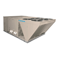
www.DaikinApplied.com 39 IM 972-2 • MAVERICK I ROOFTOP SYSTEMS
Call For Second Stage, After First Stage Established;
Starting from A.11:
1. If a call for second stage (high re) is initiated after a call
for rst stage heat is established, the control energizes
the W2 inducers and energizes the second stage of the
gas valve.
2. Control enters normal operating loop where all inputs are
continuously checked.
Starting From B.3:
1. Once the call for second stage is satised, the control
starts a 30 second o delay on W2 inducers and reduces
the gas valve to rst stage.
2. Control enters normal operating loop where all inputs are
continuously checked.
1. Zone thermostat is satised.
2. Control de-energizes gas valve.
3. Control senses loss of ame.
4. Control initiates ve second inducer post-purge and 90
second indoor blower delay o.
5. Control de-energizes inducer blower.
6. Control de-energizes indoor blower.
7. Control in the standby mode with solid red LED.
First Stage and Second Stage Called Simultaneously:
1. Zone thermostat contacts close. A call for rst stage (low
re) and second stage (high re) heat is initiated.
2. Control runs self check.
3. Control checks the high-limit switch for normally closed
contacts, each pressure switch for normally open
contacts, and all ame rollout switches for continuity.
4. Control energizes each low-re inducer.
5. Control checks each pressure switch for closure.
6. If each pressure switch is closed, the control starts a 30
second prepurge and energizes W2. If either switch is
still open, the inducers will continue to be energized until
closure.
7. After prepurge time-out, control energizes W1 and
continues to energize W2, initiates spark for 2 seconds
minimum, 7 second maximum ignition trial, and initiates
120 second stage warm up timing.
8. Control detects ame, de-energizes spark and starts a
45 second indoor blower delay on timing.
9. After a xed 45 seconds indoor blower delay on, the
control energizes the indoor blower.
10. After a xed 120 seconds second stage warm-up period
control checks the thermostat input. If W1 and W2 are
present, control enters normal operating loop where all
inputs are continuously checked.
First Stage and Second Stage Removed Simultaneously:
1. Upon a loss of W1 and W2 the gas valve is de-
energized.
2. Upon a loss of ame, each inducer will complete a 5
second post-purge and the indoor blower will complete a
90 second delay o.
3. Control in the stand by mode with solid red LED.
The integrated control is a three ignition system.
After a total of three cycles without sensing main burner
ame, the system goes into a 100% lockout mode. After one
hour, the ignition control repeats the prepurge and ignition
cycles for 3 tries and then goes into 100% lockout mode
again. It continues this sequence of cycles and lockout each
hour until ignition is successful or power is interrupted. During
the lockout mode, neither the ignitor or gas valve will be
energized until the system is reset by turning the thermostat
to the “OFF” position or interrupting the electrical power to the
unit for 3 seconds or longer.
The circulating air blower will start and run on the heating
speed if the thermostat fan switch is in the “ON” position.
The integrated furnace control is equipped with diagnostic
LED. The LED is lit continuously when there is power to the
control, with or without a call for heat. If the LED is not lit,
there is either no power to the control or there is an internal
component failure within the control, and the control should
be replaced.
If the control detects the following failures, the LED will ash
on for approximately 1/4 second, then o for 3/4 second for
designated failure detections.
1. Flash: Failed to detect ame within the four tries for
ignition.
2. Flash: Pressure switch or induced draft blower problem
detected.
3. Flash: High limit or auxiliary limit open.
4. Flash: Flame sensed and gas valve not energized or
ame sensed with no “W” signal.
5. Flash: Overtemperature switch open.