EasyManua.ls Logo

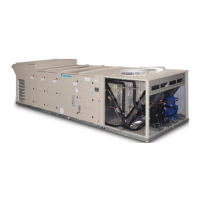
Daikin MPS026 F User Manual

Daikin MPS026 F
132 pages
To Next Page IconTo Next Page
Page #1 background imageLoading...
Page #1 background image
Installation and Maintenance Manual IM 1058-8
Group: Applied Air Systems
Part Number: IM 1058
Date: July 2017
Maverick
®
II
Commercial Packaged Rooftop Systems
Heating and Cooling
Models MPS015F – 0050F
15 to 50 Tons
R-410A Refrigerant
MicroTech
®
III Unit Controller
Energy Recovery Wheel

Table of Contents

Question and Answer IconNeed help?

Do you have a question about the Daikin MPS026 F and is the answer not in the manual?

Daikin MPS026 F Specifications

General IconGeneral
BrandDaikin
ModelMPS026 F
CategoryAir Conditioner
LanguageEnglish

Summary

General Information

Hazard Identification Information

Explains DANGER, WARNING, CAUTION symbols.

Mechanical Installation

Installer Responsibilities

Installer's duty to follow codes and regulations.

Service Clearance

Recommended clearances for unit service access.

Ventilation Clearance

Roof Curb Assembly and Installation

Procedures for installing the roof curb.

Rigging and Handling

Condensate Drain Pipe Connection

Cabinet Weather Protection

Installing Ductwork

Installing Duct Static Pressure Sensor Taps

Installing Building Static Pressure Sensor Taps

Building Pressurization Applications

Installing sensor taps for building pressurization.

Lab Pressurization Applications

Installing sensor taps for lab pressurization.

Electrical Installation

Field Power Wiring

Guidelines for field power wiring installation.

Field Control Wiring

Optional Gas Heat

Daikin Applied Tubular Heater Series Package Heater Module

Information on the tubular heater module.

Gas Furnace Design

Installation

Flue Box

Installation of the flue box.

Outdoor Air (OA) Hood

Installation of the outdoor air hood.

Electrical

Gas Pressure Requirements

Gas Piping

Gas Piping Routing Into Unit

Procedure for routing gas supply piping into the unit.

Field Gas Heat Connections

Gas Pipe Manifold Pressure Adjustment for Natural Gas Fuel

Gas Pipe Manifold Pressure Adjustment for Propane Gas Fuel

For Two Stage Furnace

Propane pressure adjustment for two-stage furnaces.

For Modulating Furnace

Propane pressure adjustment for modulating furnaces.

Sequence of Operation (Staged Control)

Low Heat Option (2 Stage Control)

Sequence of operation for low heat staged control.

High Heat Option (4 Stage Control)

Sequence of operation for high heat staged control.

Sequence of Operation (Modulating Burner)

Start-Up Procedures

Start-Up Responsibility

Responsibilities during unit start-up.

Ignition Control Module for Staged Gas Furnace

Ignition Control Module for Modulating Gas Furnace (240 MBH Furnace Only)

Ignition Control Module LED Diagnostics

Diagnosing faults using LED indicators.

Ignition Control Module for Modulating Gas Furnace (300 & 400 MBH Furnace Only)

Ignition Control Module LED Diagnostics

Optional Electric Heat

Electric Heater Design

Design and safety features of electric heaters.

Optional Modulating Hot Gas Reheat

Dehumidification Initiation

Dehumidification Termination

Control & Arrangement

Optional Hot Water Heat

Optional Energy Recovery Wheel

Energy Recovery Wheel Design

Overview of the enthalpy wheel energy recovery system.

Purge and Pressurization

Frost Protection Option

Constant Speed Frost Prevention

Variable Speed Frost Prevention

Variable Speed Frequency Control

Optional Outdoor Air Monitor

Converting the Analog Output Signal from FPM to CFM (MPS to LPS for SI units scaling)

Proof-of-Airflow and Dirty Filter Switch

Duct High Pressure Limit

Condenser Fan Operation for Variable Speed Compressor Low Ambient Option (MPS 040 and 050 Only)

VFD Compressor Operation

VFD Compressor Control

VFD Compressor Protection Unloading Control

High Pressure Unloading Control

Control to reduce speed if discharge pressure is too high.

High Discharge Line Temperature Unloading Control

Low/High Discharge Superheat

Low Superheat

Adjusting speed for low superheat conditions.

High Superheat

Adjusting speed for high superheat conditions.

Manual Control (with VFD Compressor)

Condenser Coil Splitter Solenoid Valve Control (MPS 040 and 050 Only)

VFD Compressor Emergency Stop Control

Variable Speed Scroll Compressor

Variable Speed Scroll Compressor Operation

How variable speed compressors operate.

Oil Injection Control

Optical Oil Level Sensor

Electrical Connections and Wiring

Variable Frequency Drive for VFD Compressor

VFD Compressor Operation

Basic operation of the compressor drive.

Sequence of Operation

Heating

Unit operation during heating mode.

Mechanical Cooling

Constant Volume (Space Comfort Controller)

Cooling control for CAV units using space temperature.

Variable Air Volume (Discharge Air Controller)

Cooling control for VAV units using discharge air temp.

Economizer

Check, Test, and Start Procedures

Pre-Start of Unit

Procedures to ensure proper unit operation after installation.

Power-Up

Fan Start-Up

Economizer Start-Up

Compressor Start-Up

Scroll Compressor Rotational Direction

Checking Subcooling

Expansion Valve Superheat Adjustment

Checking Superheat

Sheave Alignment

Drive Belt Tension Adjustment

Air Balancing

Energy Recovery Wheel

Final Control Settings

Controller Settings for Normal Operation

Setting controller parameters for normal unit operation.

Maintenance

Performing Service Maintenance

Guidelines for qualified personnel performing service.

Planned Maintenance

Routine inspections and tasks to prevent issues and ensure longevity.

Connecting the Condenser Coil to Copper Tubing

Routine Quarterly Cleaning of Option E Coated Coil Surfaces

Control Panel Components

Thermal Overload Relay

Circuit Breaker

Phase Voltage Monitor (PVM)

Through-the-Door Disconnect

Bearing Lubrication

Periodic Service and Maintenance

Segment Installation & Replacement

Wheel Drive Motor & Pulley Replacement

Belt Replacement

Troubleshooting

Supply Fan

Servicing Refrigerant Sensors or Switches

Servicing Optional Electric Heater

Service and Warranty Procedure

Rooftop Equipment Warranty Registration Form (continued)

III. START-UP COMPRESSOR OPERATION

IV. PERFORMANCE DATA

V. ELECTRIC HEAT CHECK, TEST & START

VI. GAS BURNER CHECK, TEST, & START

S. Modulation Gas Heat Performance

Related product manuals