EasyManua.ls Logo

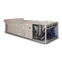
Daikin MPS040 F User Manual

Daikin MPS040 F
132 pages
To Next Page IconTo Next Page
Page #1 background imageLoading...
Page #1 background image
Installation and Maintenance Manual IM 1058-8
Group: Applied Air Systems
Part Number: IM 1058
Date: July 2017
Maverick
®
II
Commercial Packaged Rooftop Systems
Heating and Cooling
Models MPS015F – 0050F
15 to 50 Tons
R-410A Refrigerant
MicroTech
®
III Unit Controller
Energy Recovery Wheel

Table of Contents

Question and Answer IconNeed help?

Do you have a question about the Daikin MPS040 F and is the answer not in the manual?

Daikin MPS040 F Specifications

General IconGeneral
BrandDaikin
ModelMPS040 F
CategoryAir Conditioner
LanguageEnglish

Summary

General Information

Hazard Identification Information

Dangers, warnings, and cautions for unit operation.

Mechanical Installation

Installer Responsibilities

Installer's duties and adherence to codes.

Service Clearance

Recommended clearances for unit maintenance.

Assembly Instructions

Rigging and Handling

Installing Ductwork

Field Control Wiring

Optional Gas Heat

Installation

IMPORTANT

Requirements for furnace installation by qualified personnel.

Gas Piping

Sequence of Operation (Staged Control)

Low Heat Option (2 Stage Control)

Sequence for low heat staged operation.

Start-Up Procedures

DANGER

Fire or explosion hazard warning for gas appliance.

Maintenance

Planned Maintenance

Planned maintenance recommendations and intervals.

Ignition Control Module for Modulating Gas Furnace (240 MBH Furnace Only)

Ignition Control Module LED Diagnostics

Using LED indicators to diagnose faults.

Electric Heater Design

Optional Modulating Hot Gas Reheat

Control & Arrangement

Optional Hot Water Heat

Optional Energy Recovery Wheel

Energy Recovery Wheel Design

How the enthalpy wheel provides energy recovery.

Purge and Pressurization

Optional Outdoor Air Monitor

Table 25: General Troubleshooting

Condenser Fan Operation for Variable Speed Compressor Low Ambient Option (MPS 040 and 050 Only)

Daikin’s head pressure control

How head pressure control operates with VFD compressors.

VFD Compressor Operation

VFD compressor modulation

Control of VFD compressor speed via analog signal.

VFD Compressor Control

VFD Compressor Protection Unloading Control

Low/High Discharge Superheat

Condenser Coil Splitter Solenoid Valve Control (MPS 040 and 050 Only)

Variable Speed Scroll Compressor

Variable Frequency Drive for VFD Compressor

WARNING

Warning against bypassing or modifying the VFD.

Wiring Diagrams

Figure 67: MPS 030–050 VAV Control with Variable Speed Inverter Compressor

Mechanical Cooling

Check, Test, and Start Procedures

Fan Start-Up

Scroll Compressor Rotational Direction

Expansion Valve Superheat Adjustment

Energy Recovery Wheel

Final Control Settings

Controller Settings for Normal Operation

Setting parameters for normal unit operation.

Performing Service Maintenance

Control Panel Components

Thermal Overload Relay

Bearing Lubrication

Routine Maintenance

Segment Installation & Replacement

Belt Replacement

Supply Fan

Service and Warranty Procedure

Rooftop Equipment Warranty Registration Form (continued)

Rooftop Equipment Warranty Registration Form (continued)

IV. PERFORMANCE DATA

Recording performance data during start-up.

V. ELECTRIC HEAT CHECK, TEST & START

Procedures for checking electric heat operation.

Appendix – Keypad/Display Menu Structure

Related product manuals