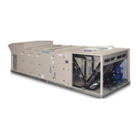
Rigging and Handling
WARNING
Only trained and qualied personnel should be allowed to rig
loads or operate load rated cranes and/or hoist assemblies.
Do not use a forklift to lift or maneuver the unit. Failure to use
a load rated crane or hoist assembly to lift or maneuver the
unit can cause severe personal injury and property damage.
WARNING
Use all lifting points. Improper lifting can cause property
damage, severe pers al injury, or death.
CAUTION
Lifting points may not be symmetrical to the center of gravity
of the unit. Ballast or unequal cable lengths may be required.
Rigging holes for shackles are integral on the unit base. All
six lifting points must be used for rigging the equipment.
Use four independent lines, securing one end of a line
to a unit base lifting point and the other end of the line
to an associated spreader bar lifting point (see Figure 10
and Figure 11). Figure 9 is an example of an instruction label
shipped with each unit.
Figure 9: Rigging Label
Use spreader bars, 96" to 100" (2438 to 2540 mm) wide to
prevent damage to the unit cabinet. Avoid twisting or uneven
lifting of the unit. The cable length from the bracket to the hook
should always be longer than the distance between the outer
lifting points.
If the unit is stored at the construction site for an intermediate
period, take these additional precautions:
1. Support the unit well along the length of the base rail.
2. Level the unit (no twists or uneven ground surface).
3. Provide proper drainage around the unit to prevent
ooding of the equipment.
4. Provide adequate protection from vandalism, mechanical
contact, etc.
5. Securely close the doors.
6. Cover the supply and return air openings.
Table 4 and Table 5 lists the weight distribution at each of the
lifting points on the unit (refer to Figure 10 and Figure 11). Table
6 details lifting point locations. Table 7 through Table 12 lists the
weights of unit curbs and other sections of the unit.
Table 2: Unit Base Weights
Unit (Tons) Total Weight (lbs)
015 2655
017 2705
020 3610
026 3610
030 3610
035 3660
040 4685
050 4985
Table 3: Unit Curb Weights
Unit (tons) Curb Height (inches) Total Weight (lbs)
Standard Unit
015–035
14 341
24 504
040–050
14 461
24 706
Unit with Energy Wheel
015–035
14 458
24 674
040–050
14 619
24 908
LIFT UNIT ONLYAS SHOWN
SPREADER BARS REQUIRED
MUST USE ALL OF THESE
LIFTING LUGS FOR LIFTING UNIT.
meChanICal InsTallaTIon
www.DaikinApplied.com 13 IM 1058-8 • MAVERICK II ROOFTOP SYSTEMS

 Loading...


