3 | Components
Service manual
193
RXM20~71R + ARXM25~71R + FTXM20~71R + ATXM25~50R +
FVXM25~50A
Split New Perfera R32
ESIE20-11 – 2021.01
8 Disconnect the thermistor from the intermediate connector and measure the
resistance of the thermistor (between the appropriate pins of the connector).
Does the measured resistance of the
thermistor match with the
temperature determined resistance?
Action
Yes Correct the wiring between the
thermistor connector on the PCB and
the intermediate connector, see
"6.2Wiring diagram"[4223].
No Replace the specific thermistor, see
"Repair procedures"[4193].
3.19.2 Repair procedures
To remove the thermistor
Indoor unit air (room) thermistor
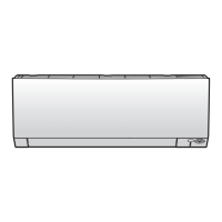
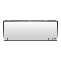
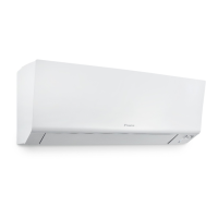
WALL MOUNTED INDOOR UINTS
As the indoor unit air (room) thermistor is located on the display PCB, remove the
display PCB as described in the steps below:
Prerequisite: Stop the unit operation via the user interface.
Prerequisite: Turn OFF the respective circuit breaker.
Prerequisite: Remove the required plate work, see "3.14Plate work"[4151].
1 Remove the display panel from the indoor unit.
2 Pull up the bottom of the indication lamp cover.
a Indication lamp cover
b Display PCB
3 Remove the display PCB from the back side of the indication lamp cover.
4 Disconnect the connector from the display PCB.
5 To install the indoor unit air (room) thermistor, see "Repair
procedures"[4193].
FLOOR STANDING INDOOR UNITS
Procedure is similar as for the outdoor unit air thermistor, see below.

 Loading...


