IM 1287-6 • REBEL APPLIED ROOFTOP 50 www.DaikinApplied.com
Table 6: Cold Water Connection Sizes
Code 004 (Pos 5-7)
B24 B29 B34 C34 C39 C44
Code
009
(Pos 12)
T 2-½" 2-½" 2" 2" 2" 2"
U 2-½" 3" 2-½" 2-½" 2-½" 2-½"
V 2" 2-½" 2" 2" 2" 2"
W 2-½" 3" 2-½" 2-½" 2-½" 2-½"
Y 3" 3" 2-½" 2-½" 3" 3"
1 2-½" 2-½" 2" 2" 2-½" 2-½"
2 3" 3" 2-½" 2-½" 3" 3"
3 3" 3" 3" 3" 3" 3"
4 2-½" 2-½" 2" 2" 2-½" 2-½"
5 3" 3" 2-½" 2-½" 3" 3"
6 3" 3" 3" 3" 3" 3"
7 2-½" 2-½" 2" 2" 2-½" 2-½"
8 3" 3" 2-½" 2-½" 3" 3"
9 3" 3" 3" 3" 3" 3"
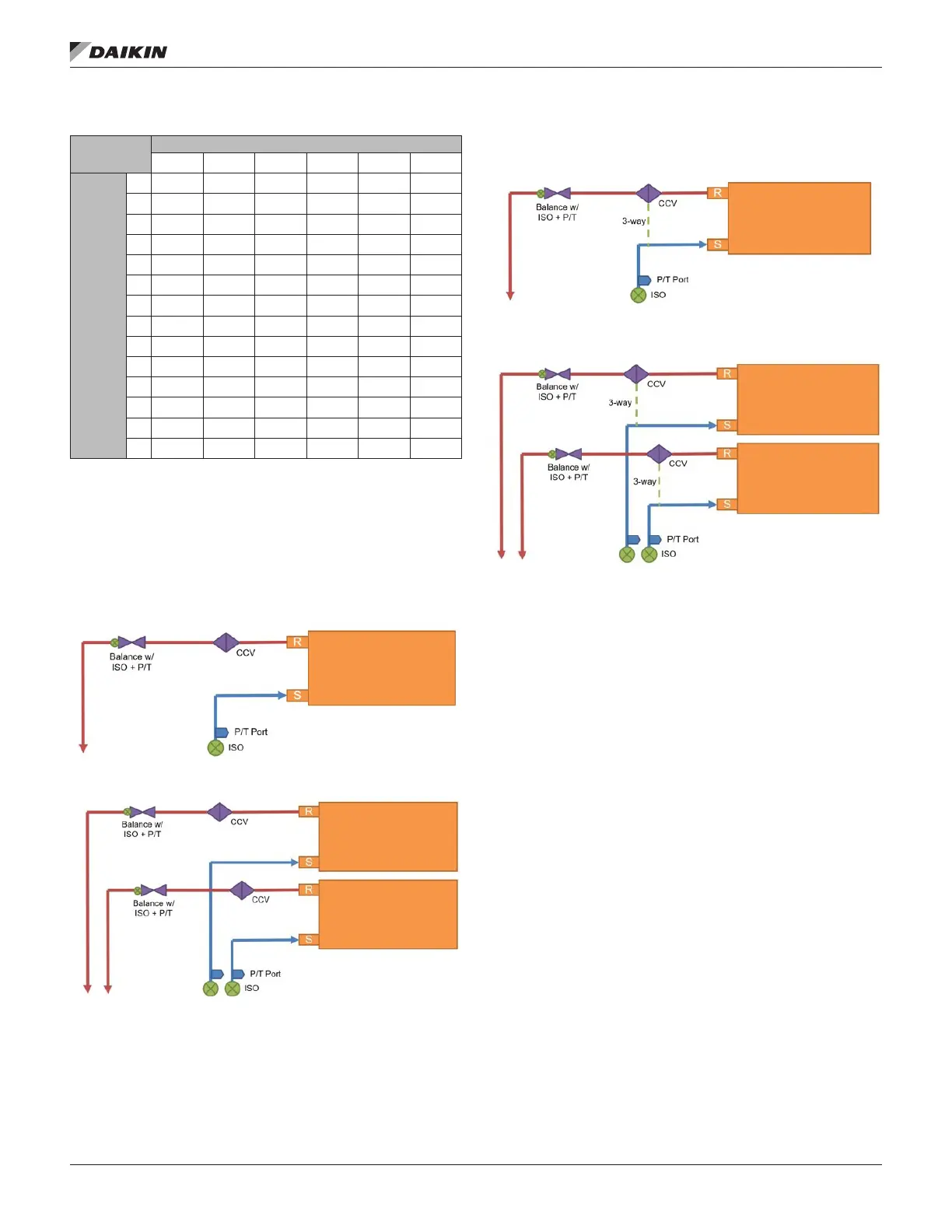
The contents of Table 6 show the connection piping sizes
based on the coil selection. Valve package connections
are F-NPT and will require a tapered pipe eld connection
(M-NPT). Header connection points are straight pipe and will
require a coupling (F-SWT).
Figure 91: Chilled Water 2-Way Valve Options
Single Coil 2-Way
Stacked Coil 2-Way
Figure 92: Chilled Water 3-Way Valve Options
Single Coil 3-Way
Stacked Coil 3-Way
 Loading...