IM 1287-6 • REBEL APPLIED ROOFTOP 54 www.DaikinApplied.com
HEPA Holding Frame, Filter, and
WARNING
Sharp edges on sheet metal and fasteners can cause personal injury.
Please wear appropriate personal protective equipment (PPE) such as
gloves, protective clothing, footwear, eye protection, etc. This equipment
must be installed, operated, and serviced only by an experienced installation
company and fully trained personnel.
These instructions are for installing AAF HEPA lters (11-1/2”
depth) into AAF HEPA Holding Frames.
Please read the entire installation instructions before beginning
the installation process.
Install lters into the HEPA Holding Frames only after the
frames have been securely installed into existing ductwork
or housing. Frames should be bolted or pop riveted together
into the permanent structure through the pre-drilled holes
around the outside perimeter of the frames. Frames should be
suciently caulked and sealed to prevent any air bypass or
leakage.
Required tools for lter installation:
• T-handle Hexkey, size 5/32”
Framing Components Required:
• AAF HEPA Holding Frames
— P/N 910111491 & 910111674
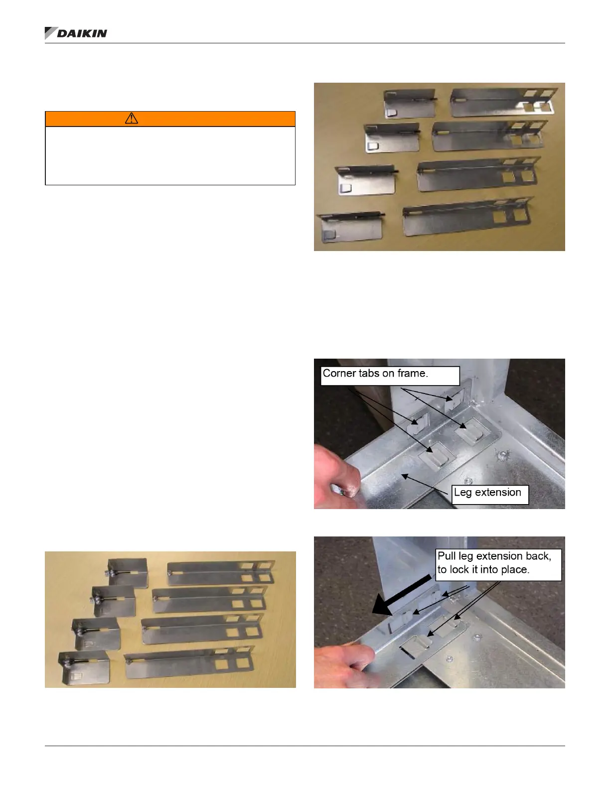
• Leg Extensions, 4 per frame (A)
— P/N 910111494
• Latches, 4 per frame
— P/N 910111493 (B) (without prelters)
— P/N 910123164 (C) (with prelters)
• Prelter Holding Frames (when prelters are ordered)
— P/N 910123166 & 910123168
• Prelter Latches (when prelters are ordered)
— P/N 111048304 & 111048305
Figure 99: Leg Extensions and Latches Without Prelters
Figure 100: Leg Extensions and Latches With Prelters
STEP 1: At the inside corner of each frame are 4 tabs, 2 per
side. Place a leg extension over the 4 tabs as shown in Figure
101, then pull back on the leg extension locking it into place
(Figure 102).
Figure 101: Place Leg Extension Over the Frame Tabs
Figure 102: Pull Back to Lock the Leg Extension Into Place
A
A
A
A
B
B
B
B
A
A
A
A
C
C
C
C


 To Next Page