IM 1287-6 • REBEL APPLIED ROOFTOP 56 www.DaikinApplied.com
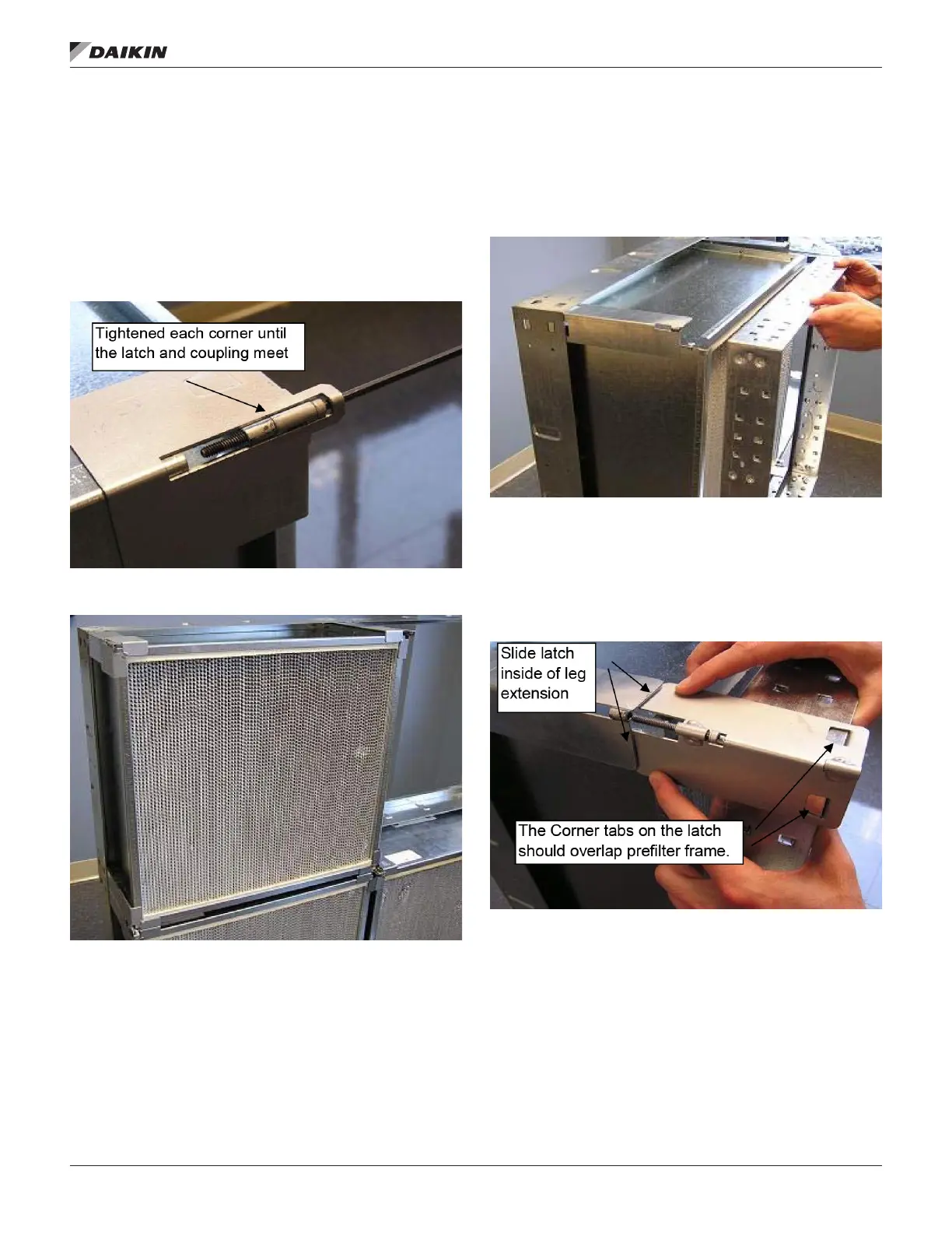
STEP 4: Once all four corner latches have been tightened
within 1/4” of the leg extension coupling, complete the
installation by tightening each corner until the latch and leg
extension coupling meet. This is illustrated in Figure 108.
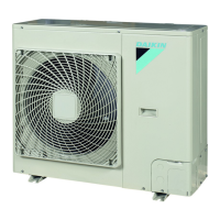
Once all four corners have been tightened the lter should now
be properly seated and sealed.
Repeat the process with all remaining lters working from the
bottom to the top.
Figure 108: Tighten Until Latch and Coupling Meet
Figure 109: Properly Installed Filter Inside of the Frame
Follow previous steps 1-2, then continue straight to step 5.
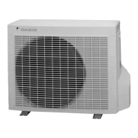
STEP 5: The prelter holding frame should be placed directly
in front of the HEPA lter as shown in Figure 110.
Figure 110: Positioning of the Prelter Frame
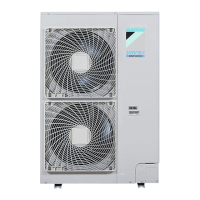
STEP 6: Place a latch so that the 2 tabs of the latch overlap
the prelter frame on each side of the corner. Slide the latch
inside of the leg extension and align the latches’ cap screw
with the threaded coupling on the end of the leg extension and
tighten using the hexkey. See Figure 111.
Figure 111: Latch Positioning for Prelter Frame
Tighten the cap screw until there is an approximately 1/4” gap
between the latch and the leg extension coupling as shown in
Figure 112. Repeat this step with all 4 corners.