www.DaikinApplied.com 63 IM 1287-6 • REBEL APPLIED ROOFTOP
Installing Building Static Pressure
Sensor Taps
CAUTION
Please be careful when removing tubing from the fragile pressure sensor
tting. Do not use excessive force or wrench the tubing back and forth
when removing the tubing. Excessive force and motion can break off and
damage the sensor.
Units that are selected with the capability for direct building
static pressure control require a reading of the building static
pressure. This requires that pressure taps be eld installed and
plumbed back to the Building Static Pressure sensor (BSP) in
the unit. When present, the BSP sensor is found in the Low
Voltage Control Panel.
Carefully locate and install the eld provided pressure taps.
Improperly locating or installing the BSP pressure taps may
result in unsatisfactory operation. Consider the following
pressure tap locations and installation recommendations.
The installation must comply with all applicable local code
requirements.
1. Install a tee tting with a leak-tight removable cap in each
tube near the sensor tting. This facilitates connecting a
manometer or pressure gauge if testing is required.
2. Dierentiate between the building pressure (HI) and
outdoor pressure (LO) taps by using dierent color tubing
or by tagging the tubes. Daikin Applied recommends
3/16ʺ I.D. plastic tubing.
3. Regardless whether the pressure in the controlled space
is to be positive or negative with respect to its reference,
the building pressure tap will be the HI pressure tap on
the Building Static Pressure sensor.
4. Locate the building pressure (HI) tap in the area that
requires the closest control. Typically, this is a ground
level oor that has doors to the outside. The location
must not allow the reading to be inuenced by any
source of moving air (velocity pressure). These sources
may include air diusers or outside doors.
5. Route tubing between the building pressure tap and
the Building Static Pressure sensor (HI) tap. The tubing
should be routed between the curb and the supply duct,
entering into the Main Control Panel through the Panel
Entrance Plate. See Figure 118 on page 58 for the
recommended route for eld installed tubing to the BSP.
6. Locate the reference pressure (LO) tap in the area
surrounding the controlled space. Improperly locating the
reference tap may result in unsatisfactory operation.
7. If the reference pressure (LO) tap is to be located
outside, locate it away from condenser fans, walls,
or anything else that may cause air turbulence. The
reference pressure (LO) tap must be mounted high
enough above the roof or ground so that it is not aected
by snow. Additionally, use an outdoor static pressure
tip (Dwyer A306 or equivalent) to minimize the adverse
eects of wind. Place some type of screen over the
sensor to keep out insects. Loosely packed cotton works
well.
8. Route tubing between the reference pressure tap and
the Building Static Pressure sensor (LO) tap. The tubing
should be routed between the curb and the supply duct,
entering the Main Control Panel through the Panel
Entrance Plate. See Figure 3 on page 6 for the
recommended route for eld installed tubing to the BSP.
Seal the penetration to prevent water from entering.
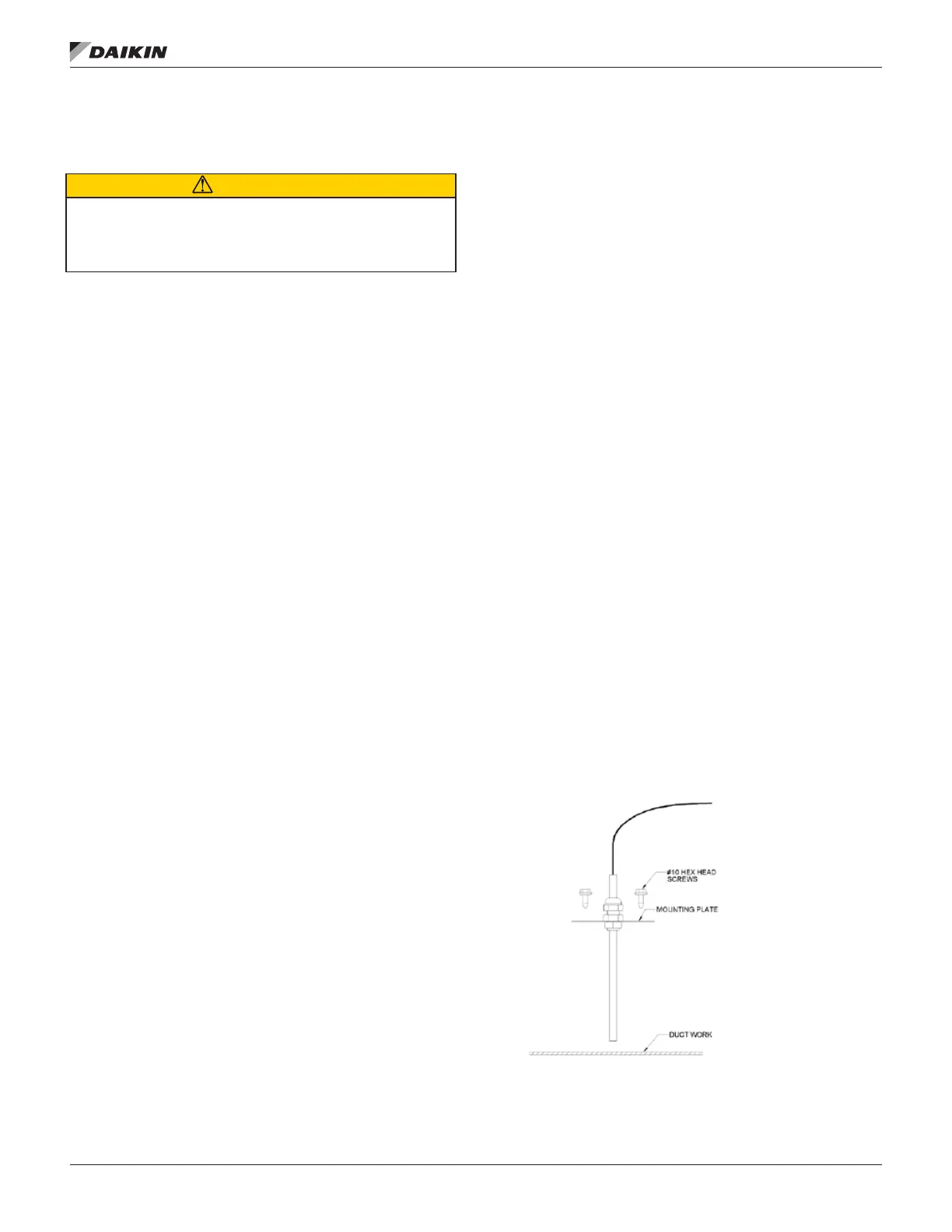
Installing Discharge Air Temperature
Sensor
The discharge air temperature sensor should be installed in
the supply air duct. downstream of the rooftop unit. Locate
the sensor at a location that approximates the average duct
temperature. Generally, locate the sensor 5-10’ from the unit
discharge and after one duct turn to allow for air mixing. Do
not install downstream of VAV boxes or other dampers.
1. Drill a 7/8” Diameter hole in the duct, insert the
temperature probe and secure plate to duct using 2-#10
screws.
2. Be sure to apply gasket or sealant to back of mounting
plate prior to screwing the plate to the duct to create an
air tight seal.
Figure 131: Temperature Sensor Installation

 Loading...