IM 1287-6 • REBEL APPLIED ROOFTOP 76 www.DaikinApplied.com
Ultraviolet Lights Option
When this option is employed, ultraviolet C light bathes
the moist surfaces on the coil and drain pan, killing most
microorganisms that can grow there.
Typically, ultraviolet lights are installed on the leaving side of
the cooling coils in the unit. Each light module is mounted on a
vertical rail and is removable for convenient bulb replacement.
UV Light Power Disconnect switches (one per door) are
factory installed on every door that allows a direct line of sight
to the UV lamps when opened. These switches are designed
to prevent UV exposure when cabinet doors are opened and
must not be disabled.
A viewing window near the UV lights allows viewing to
determine if the lights are energized. The viewing windows use
specially designed glass that blocks harmful UV light.
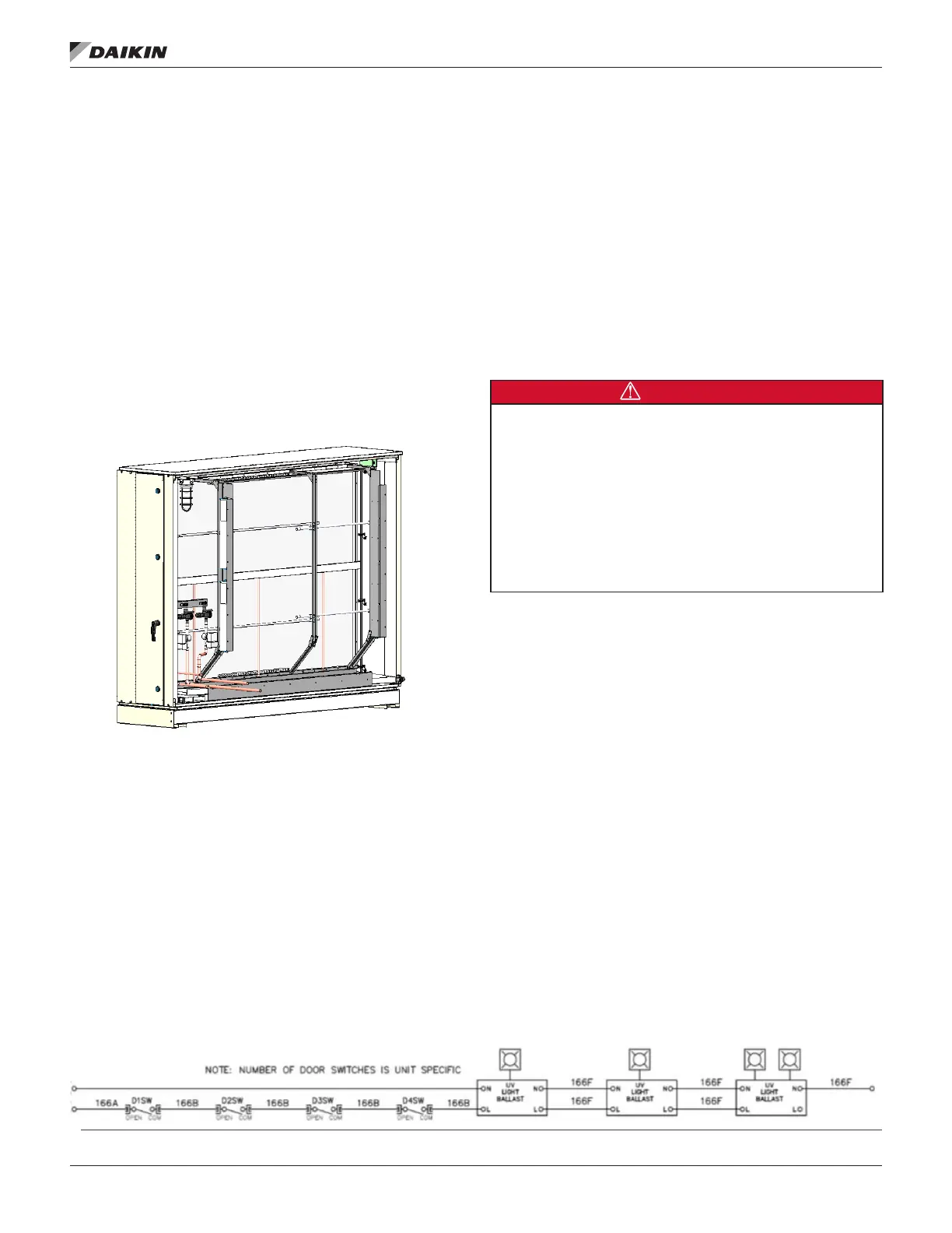
Figure 148: Typical Ultraviolet Light Installation
Ultraviolet Light Operation
The Ultraviolet (UV) Lights are powered by the main 115V
transformer and therefore will normally be on whenever the unit
is powered on. There are door switches that are installed on
some doors with access to UV radiation. These doors must be
closed for the UV lights to operate. If any one of these doors
are opened, the UV lights will lose power and turn o. When
entering the space where there may be UV light, ensure the
UV lights are o by removing power from the unit by turning o
the main power disconnect(s). Refer to Figure 149 for UV Light
control schematic. Always refer to the Unit Specic Electrical
Schematics for information regarding the number of door
switches present.
Figure 149: Typical Ultraviolet Light Wiring Schematic
Convenience Receptacle/Section Lights
A Ground Fault Circuit Interrupter (GFCI) convenience
receptacle is provided in the main control box on all units. The
receptacle can either be eld powered or unit powered. If it
is eld powered, a eld wired 120V circuit must be provided.
Refer to the Field Power Wiring section for more details. If the
receptacle is unit powered, then no additional eld wired 120V
circuit is required for it function.
If the optional service lights were included, the light switch will
be located near the GFCI receptacle. The lights are always
powered by the same source as the GFCI; either unit powered
or Field powered depending on the GFCI option selected.
Check, Test and Start Procedures
DANGER
LOCKOUT/TAGOUT all power sources before servicing this equipment.
More than one disconnect may be required to de-energize unit.
Electric shock and moving components such as, fans, dampers, energy
recovery devices can cause serious injury, death and property damage.
All start-up and service work must be performed only by trained, experienced
technicians familiar with the hazards of working on this type of equipment.
Read and follow the all relevant manuals before operating or servicing.
Bond the equipment frame to the building electrical ground through
grounding terminal or other approved means.
All units complete an end-of-line operation test at the factory
to promote proper operation in the eld. Nevertheless, the
following check, test, and start procedures must be performed
to properly start the unit. To obtain full warranty coverage,
complete and sign the check, test, and start form supplied
with the unit, or complete the “Rooftop Equipment Warranty
Registration Form” on page 172 and return it to Daikin
Applied.
A representative of the owner or the operator of the equipment
should be present during start-up to receive instructions in the
operation, care, and maintenance of the unit.

 Loading...