• Outdoor Units • R-410A • REQ-B7
• Split Sky Air • Outdoor Units
12
37
4
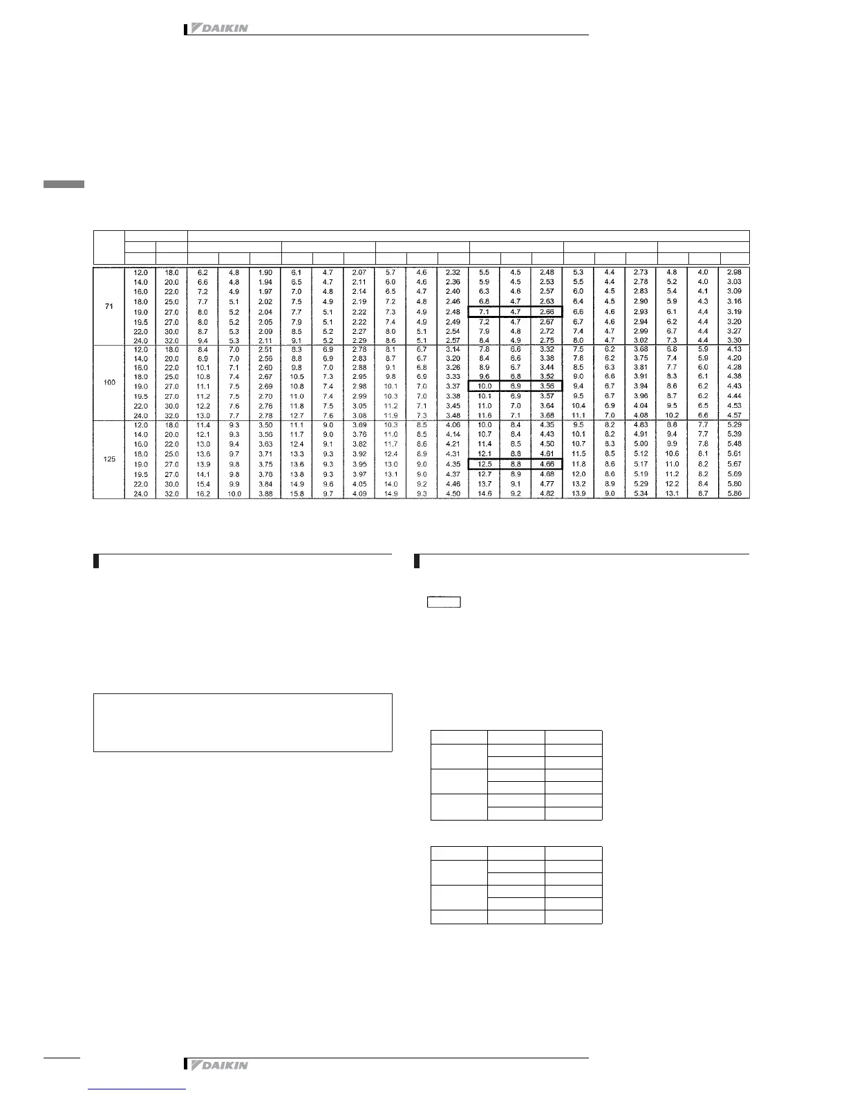
4 Capacity tables
4 - 1 Cooling capacity tables
FCQ71-125B7V3B + REQ71-100B7V3B
REQ71-125B7W1B
Cooling capacity table
Outdoor
Indoor Outdoor temp. (°CDB)
EWB EDB 20 25 32 35 40 46
(°C) (°C) TC SHC PI TC SHC PI TC SHC PI TC SHC PI TC SHC PI TC SHC PI
3TW26592-1
SYMBOLS
AFR: Air flow rate (m
3
/min)
BF: Bypass factor
EWB: Entering wet bulb temp. (°CWB)
EDB: Entering dry bulb temp. (°CDB)
DB*: Dry bulb temp. (°CDB)
TC: Total cooling/heating capacity (kW)
SHC: Sensible heating capacity (kW)
PI: Power input (kW)
(comp.+indoor+outdoor fan motor)
Caution:
TC and SHC are shown by kW
V3: 230 V [50 Hz]
W1: 400 V [50 Hz]
NOTES
1. Ratings shown are net capacities.
Influence of fan motor heat is included.
2.
Shows nominal capacities
3. SHC is based on each EWB and EDB
SHC* = SHC correction for other dry bulb
SHC* = 0.29 x 60 x AFR (m
3
/min.) x (1−BF) x (DB*−EDB)/860
Add SHC* to SHC if SHC > TC, then TC equal SHC
4. Direct interpolation is permissible.
Do not extrapolate.
5. Capacities are based on following conditions:
Corresponding refrigerant piping length : 7.5 m
Level difference : 0 m
6. Air flow rate and BF are tabulated below.
Model FCQ
71
AFR 18
BF 0.1
100
AFR 28
BF 0.16
125
AFR 31
BF 0.07
7. Add the following corrections to power input of each model.
Model Supply FCQ
71
V3 0.06
W1 0
100
V3 0.27
W1 0
125 W1 0