Printed Circuit Board Connector Wiring Diagram and Name Si18-201
60 Printed Circuit Board Connector Wiring Diagram and Name
1. Printed Circuit Board Connector Wiring Diagram
and Name
1.1 Branch Provider Unit BPMK928B42, B43
Name of Connector
Other Designations
Printed Circuit
Board
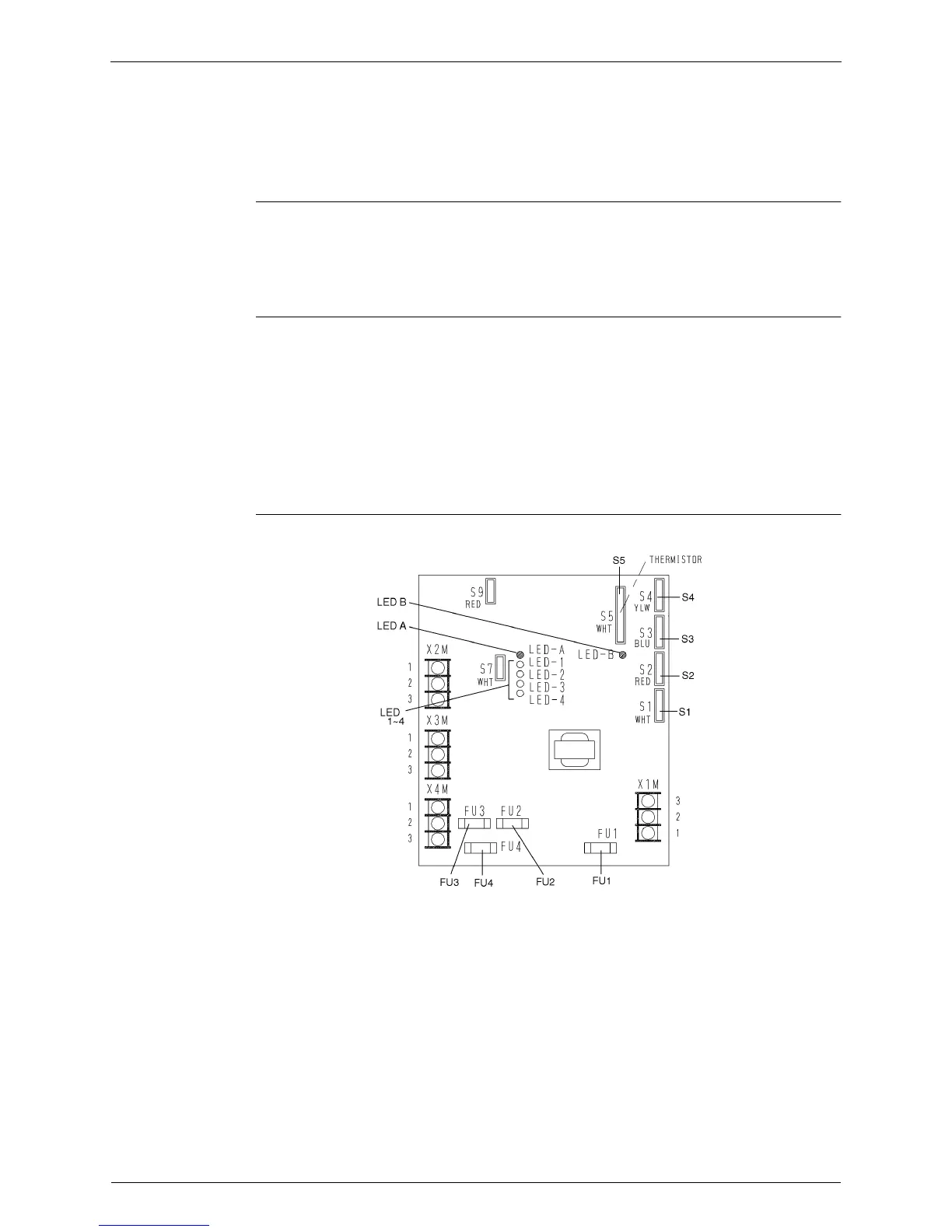
1) S1 Connector for Bypass Electronic Expansion Valve
2) S2 to S4 Connector for Electronic Expansion Valve to Room A, B and C
3) S5 Connector for Thermistors
1) FU1 Fuse for Transformer
2) FU2 Fuse for Inter Connecting Wire to Room 1
3) FU3 Fuse for Inter Connecting Wire to Room 2
4) FU4 Fuse for Inter Connecting Wire to Room 3
5) LED-A LED for Service Monitor
6) LED-B LED for Service Monitor
7) LED 1 to 4 LED for Fault Indication