Printed Circuit Board Connector Wiring Diagram and Name Si18-201
62 Printed Circuit Board Connector Wiring Diagram and Name
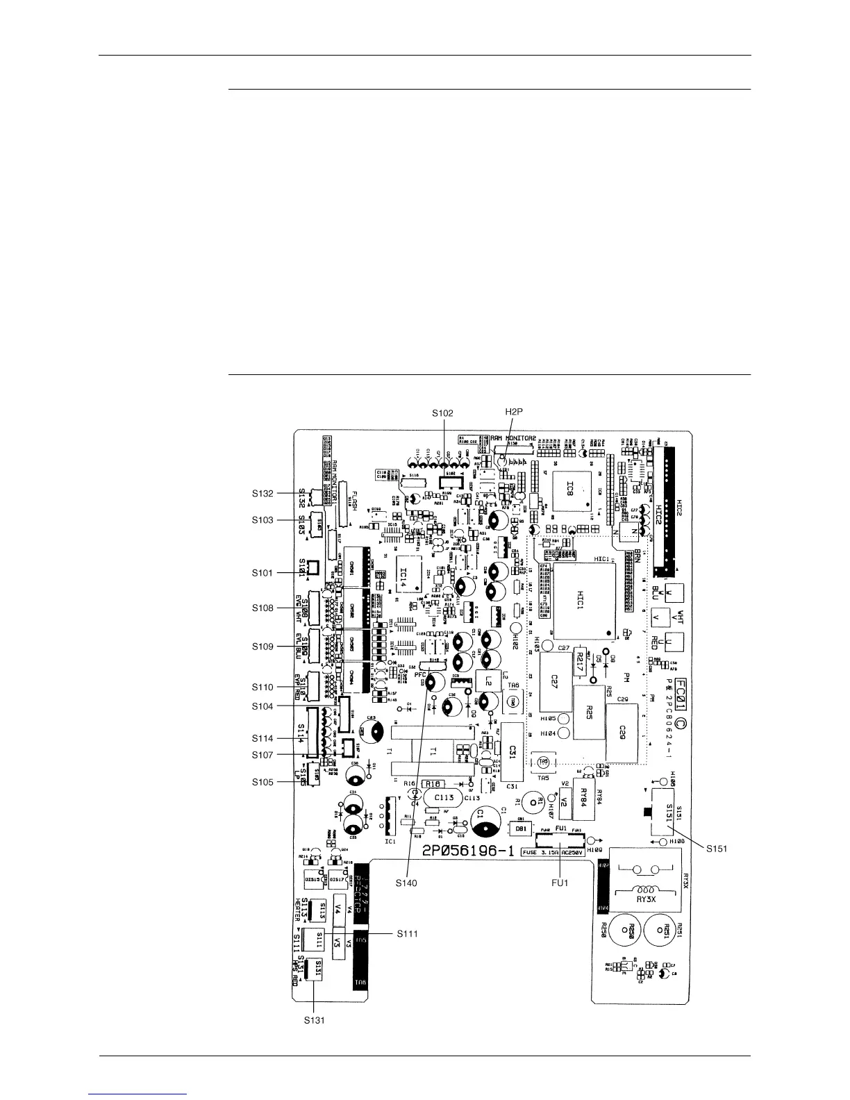
Other Designations
Printed Circuit
Board (1)
(Control PCB)
1) H1P (LED A on PCB 4) LED for Outdoor Unit Status-normal
2) H2P (PCB 1) LED for Outdoor Unit Status-normal
3) H3P (PCB 3) LED for Outdoor Unit Fan Status-normal
4) H4P (PCB 3) LED for Outdoor Unit Fan Status-normal
5) LED 2~4 (PCB 4) Digital Service Monitor
6) SW1, SW2 (PCB 4) Address Selection Switches
7) SW3 (PCB 4) Forced Operation Mode Selection Switch (Cool
↔
Heat)
8) SW4 (PCB 4) Pump Down Switch (Service Mode No. Down Switch)
9) SW5 (PCB 4) Pump Down Switch (Service Mode No. Up Switch)
10) SW6 (PCB 4) Initialize Switch
11) SW7 (PCB 4) Test Operation Switch
12) FU1 (PCB 1) Fuse 3.15Amps
13) JP Silent Select Switch