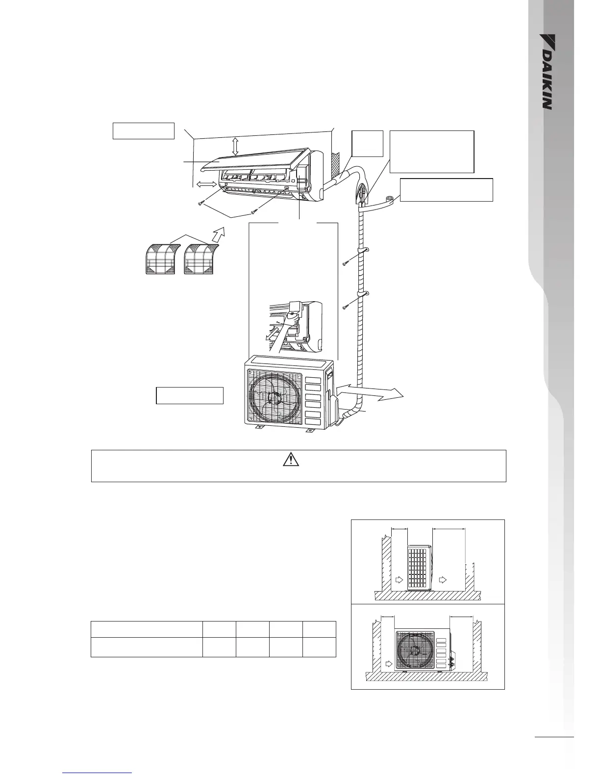
Installation Diagram
Caution
• Before installing the unit, ensure that the power supply matches the power requirement of the air conditioner.
Installation Of The Outdoor Unit
Installation Clearances
The outdoor unit must be installed in such a way, so as to
prevent short circuit of the hot discharged air or obstruction to
the smooth air flow. Please follow the installation clearances
shown in the figure. Select the coolest possible place where
intake air temperature is not greater than the outside air
temperature (please refer operating range).
Note: If there is any obstacle higher than 2m, or if there is any
obstruction at the upper part of the unit, please allow more space than
the figure indicated in the above table.
Front panel
50mm or more from walls
(on both sides)
75mm or more from ceiling
M4 x 12L
Air filter
Service lid
■
Opening service lid
Service lid is opening/
closing type.
■
Opening method
dil ecivres eht evomeR )1
screws.
dil ecivres eht tuo lluP )2
diagonally down in the
direction of the arrow.
3) Pull down.
500mm from wall
Indoor unit
Outdoor unit
Caulk pipe
hole gap
with putty.
Cut thermal insulation pipe
to an appropriate length and
wrap it with tape, making
sure that no gap is left in the
insulation pipe’s cut line.
Wrap the insulation pipe with the
finishing tape from bottom to top.
Return air
Discharge air
A
Obstacle
Obstacle
B
Obstacle
Return air
Service access
DC
Obstacle
Dimension
A B C D
Minimum Distance,
mm (in)
300
(11.8)
1000
(39.4)
300
(11.8)
500
(19.7)