IM 893-10 • ROOFPAK SINGLEZONE UNITS 86 www.DaikinApplied.com
unIT oPTIons
Making Level Adjustments
The DesignFlow unit is mounted so that it pivots at the top
when three lock nuts are loosened, two at the top and one at
the bottom of the assembly (see Figure 87). Leveling the unit
involves precisely pivoting the assembly with a known force
applied to the vane until the vane opens to a specic position.
If after performing Steps 13 through 15 above, the vane does not
come to rest within the specied range, carry out these steps:
1. Unlock and open the louvered outdoor air intake door on
the side of the unit.
2. Loosen the two 1/4-20 NC lock nuts at the top of the
DesignFlow frame. (See Figure 87.)
3. Close and lock the intake door.
4. Remove the cover from the access opening in the bottom
blade of the outdoor air intake louver (see Figure 88).
5. Loosen the 1/4-20 NC lock nut in the slotted hole at the
bottom of the DesignFlow frame. (See Figure 89.)
6. If the LH Lvl Pos= (or RH Lvl Pos=) value obtained in
step 15 above is HIGHER than the specied range,
move the bottom of the DesignFlow frame closer to the
outdoor air dampers (away from the back end of the
unit). Do this by turning the long adjuster nut to increase
the L dimension in Figure 89.
If the LH Lvl Pos= (or RH Lvl Pos=) value obtained in
step 15 above is LOWER than the specied range,
move the bottom of the DesignFlow frame away from the
outdoor air dampers (toward the back end of the unit).
Do this by turning the long adjuster nut to decrease the L
dimension in Figure 89.
NOTE: If the necessary adjustment cannot be made using
the long adjuster nut, reposition the two 1/4-20
NC jam nuts on the threaded rod to make larger
adjustments (see Figure 89).
7. When nished making the adjustments, tighten the 1/4-
20 NC lock nut in the slotted hole at the bottom of the
DesignFlow frame. (See Figure 89.)
NOTE: Make sure the leveling weight’s top thumbscrew is still
against the vertical alignment mark on the vane.
8. Gently rap the base frame to slightly vibrate the assembly
to encourage the vane to seek its equilibrium point.
9. Recheck the vane position compared to the range
specied in Step 16 above. Readjust the level as
necessary.
NOTE: If large adjustments are required to correctly level the
vane assembly, before rechecking the level, relocate
the fulcrum as described in Step 9 in DesignFlow
Station Startup on page 84.
10. When the level is correct, unlock and open the louvered
outdoor air intake door on the side of the unit and tighten
the two 1/4-20 NC lock nuts at the top of the DesignFlow
frame. (See Figure 87.)
11. Close and lock the air intake door.
12. Recheck the vane position and readjust the level as
necessary.
13. When the vane position is correct, remove the fulcrum and
replace the access opening cover in the louvered door.
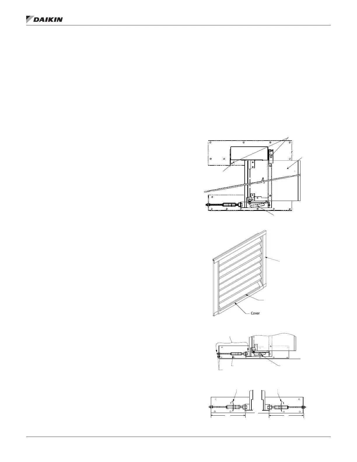
Figure 87: DesignFlow Frame
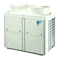
Figure 88: Remove Covers from Access Opening
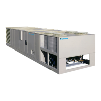
Figure 89: Leveling Adjustment
Top lock nuts
Vane
Bottom lock nut
Pivot point
Access opening
Louvered
door
assembly
Long adjuster nut
Jam nuts
Locknut
To INCREASE L dimension
L
L
Right hand adjuster Left hand adjuster