Appendix SiEN34-705
148 General Information
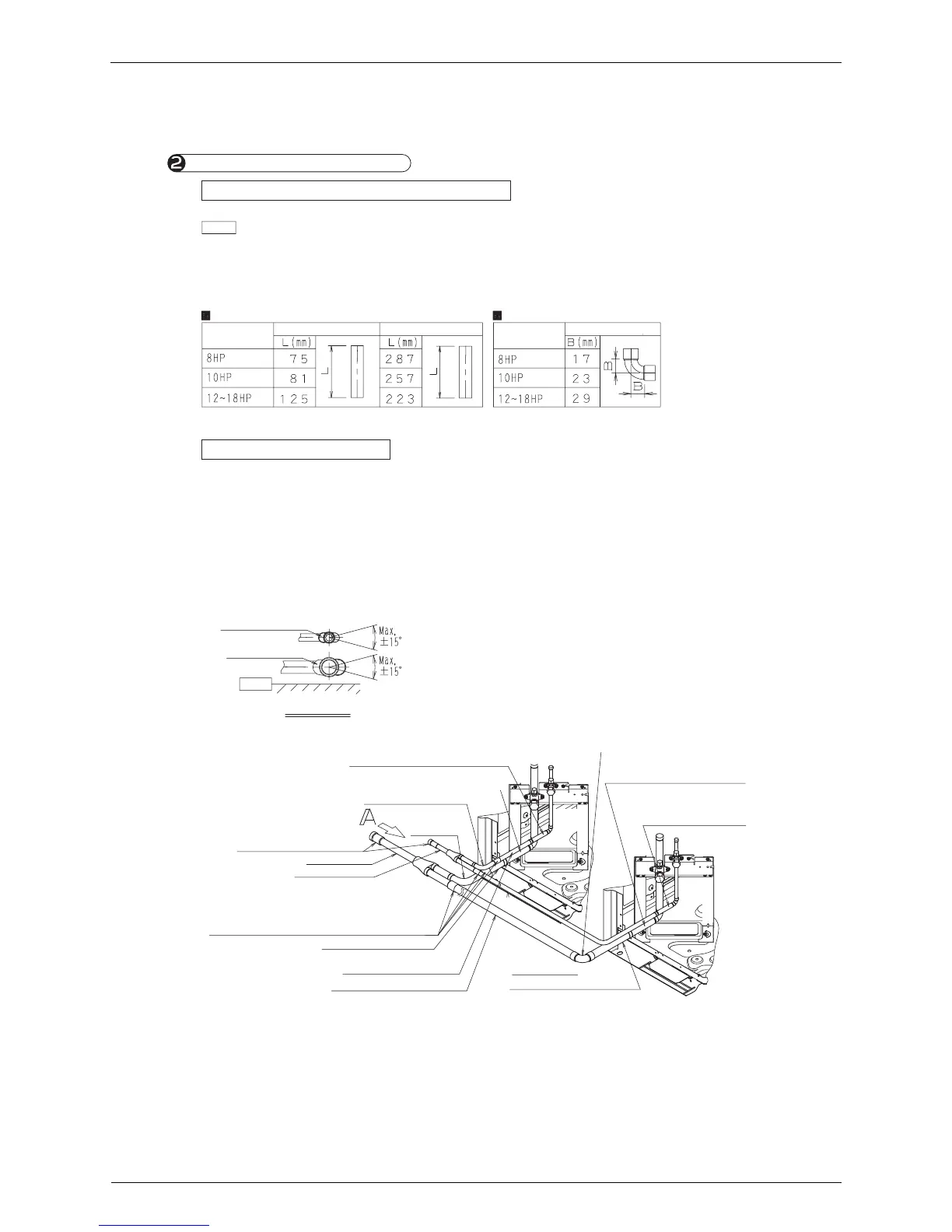
• This table shows the case when the A dimensions shown in 1-2 Finished dimensions is 290 mm.
If the A dimensions exceed 290 mm, see Table 1 and adjust the dimensions of the gas pipe
1 and 2.
• The L dimensions of the gas pipe 2 in Table 1 show those when the field supply elbows
have B dimension in Table 2. If the B dimension is not same with Table 2, see Table 1 and 2, and
adjust them accordingly.
Gas pipe 1 (field supply)
Caution
Connection of gas and liquid pipes
• Cut the pipes according to Table 1.
2-1 Cutting the field supply gas pipes
View ⺑
Liquid-side joint
2-2 Connection of pipes
• Connect the gas and liquid pipes as shown in the figure
at the right. (When connecting the pipes, first connect
the gas-side joint and the gas-side reducer (1),
the liquid-side joint and the gas-side reducer (1)
• See 1-2 Finished dimensions for the location (height) of
the joint.
• See the caution section in the installation manual
attached to the outdoor unit for brazing pipes and
connecting pipes with flare nuts.
• Install the joint in such a way that the attached face of
the caution label becomes horizontal
(See the View A)
Gas-side joint
Ground
Refer to the main pipe of
Connecting pipe sizes and
location of cutting the joint in
BHFP22P100 installation
Instructions when cutting.
Gas pipe (field supply)
(Select the pipe length on site)
Gas pipe 1 (field supply)
(As per Table 1)
Liquid pipe (field supply)
Liquid pipe
(field supply)
Gas pipe 2 (field supply)
(As per Table 1)
Refer to the pipe between the Outdoor unit Multi Connection
Piping Kit and the outdoor unit of “Connecting pipe sizes
and location of cutting the joint in BHFP22P100 installation
Instructions” when cutting.
(Attached to the outdoor unit)
Liquid-side accessory pipe assy (1)
(Attached to the outdoor unit)
Gas-side accessory pipe assy (1)
Liquid-side reducer (1)
Gas-side
reducer (1)
Gas-side joint
Liquid-side joint
(Attached to the outdoor unit)
Gas-side accessory pipe
assy (1)
(Attached to the outdoor unit)
Liquid-side accessory
pipe assy (1)
Elbow (field supply)
(As per Table 2)
Gas pipe 2 (field supply)
Elbow (field supply)
Model typeModel type
Table 2
Table 1
Outdoor
unit A
Outdoor
unit B