Appendix SiEN34-705
156 General Information
Liquid-side reducer (1)
Outdoor
unit A
Outdoor
unit B
Outdoor
unit C
Liquid-side joint (1)
Gas-side joint (2)
Gas-pipe 1 (field supply)
Gas-pipe (field supply)
Gas-pipe (field supply)
Gas-pipe 4 (field supply)
Gas-pipe 2 (field supply)
Gas-pipe 3 (field supply)
Gas-pipe 5 (field supply)
Elbow (field supply)
Gas-pipe 4 (field supply)
Elbow (field supply)
Elbow (field supply)
Gas-side joint (1)
Gas-side reducer (1)
Liquid-side reducer (1)
Liquid-side joint (2)
Liquid-pipe (field supply)
Liquid-pipe (field supply)
Liquid-pipe (field supply)
To indoor unit
Gas-side reducer (1)
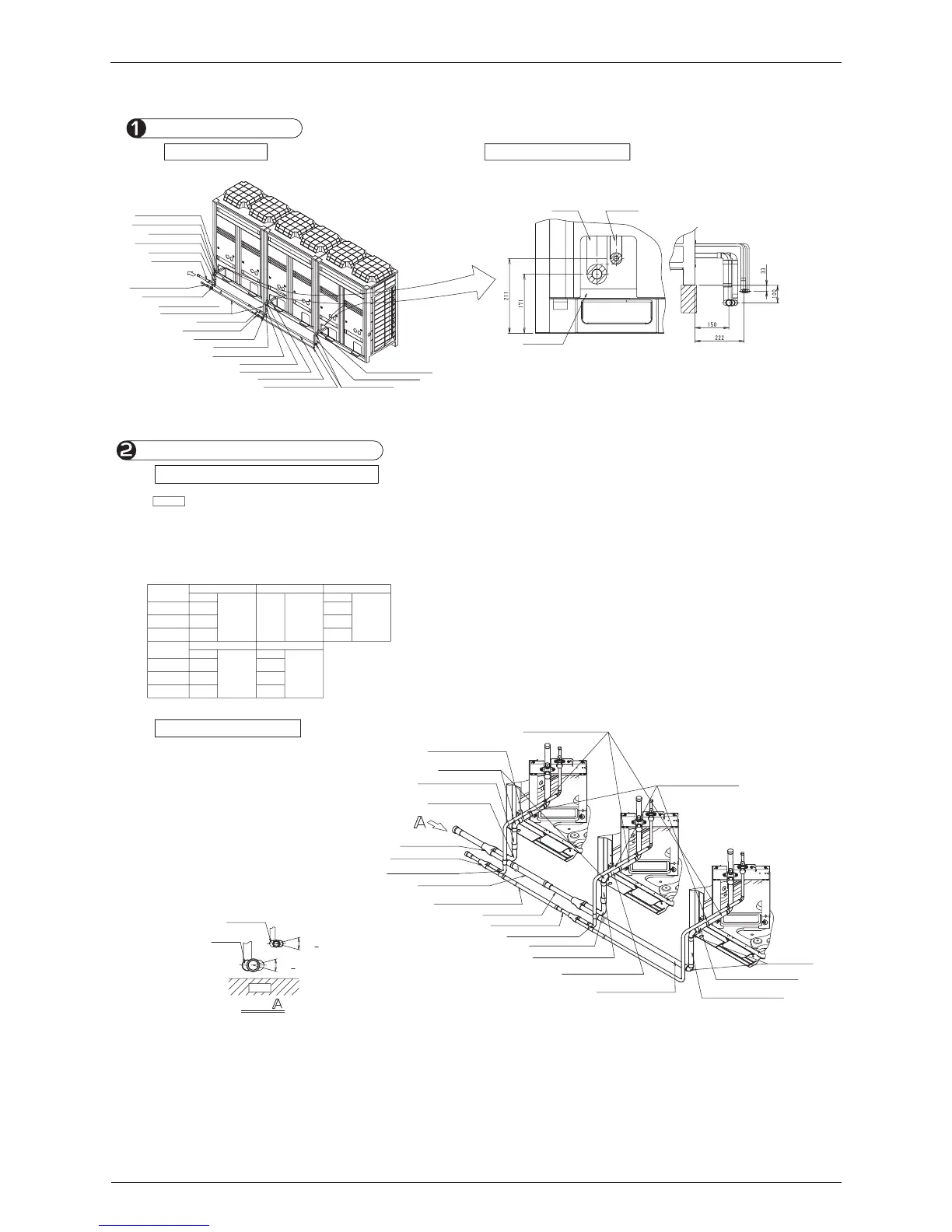
Installation examples
Procedure for Front Connection
1-1 Exterior view 1-2 Finished dimensions
• A standard installation has the following dimensions.
• When the dimensions exceed the standard installation, extend the pipes
between the outdoor unit and the joint. (field supply)
Gas-pipe
Liquid-pipe
Bottom frame
2-1 Cutting the field supply gas pipes
CAUTION
• Cut the pipes according to Table 7.
• The L dimensions of the gas pipe 1 to 5 in Table 7 show those when the field supply elbows have
B dimension in Table 2 shown in BHFP22P100 Installation instruction, 2 connection of gas and
liquid pipes and the field supply joint for the same diameter pipes are without stopper.
If the B dimensions are not the same with Table 2 or the joint for the same diameter pipes have
stopper, see Table 2 and 7, and adjust them accordingly.
Connection of gas and liquid pipes
Table 7
Gas pipe 1 (field supply) Gas pipe 2 (field supply) Gas pipe 3 (field supply)
Model type
L(mm L(mm) L(mm)
8HP 130 147 182
10HP 100 117 152
12~18 HP 66 83 118
Gas pipe 4 (field supply) Gas pipe 5 (field supply)
Model type
L(mm L(mm)
8HP 59 237
10HP 83 225
12~18 HP 149 213
Gas-side accessory pipe (1)
(Attached to the outdoor unit)
Gas-side reducer (1)
Gas-side joint (1)
Liquid-side joint (2)
Liquid-side joint (1)
Liquid-side reducer (1)
Outdoor
unit A
Outdoor
unit B
Outdoor
unit C
Gas pipe (field supply)
(Select the pipe length on site)
Gas pipe 1 (field supply)
(As per Table 7)
Gas pipe 4 (field supply)
(As per Table 7)
Gas pipe 2 (field supply)
(As per Table 7)
Gas pipe 3 (field supply)
(As per Table 7)
Gas pipe 5 (field supply)
(As per Table 7)
Gas pipe 4 (field supply)
(As per Table 7)
Gas pipe (field supply)
(Select the pipe length on site)
Elbow (field supply)
Liquid pipe (field supply)
Liquid pipe (field supply)
Gas-side joint (2)
Gas-side reducer (1)
Liquid-side reducer (1)
Elbow
(field supply)
2-2 Connection of pipes
• Connect the gas and liquid pipes as shown in the figure
at the left.
(When connecting the pipes, first connect the gas-side
joint and the gas-side reducer(1), the liquid-side joint and
the liquid-side reducer (1).)
• See the caution section in the installation manual
attached to the outdoor unit for brazing pipes and
connecting pipes with flare nuts.
• Install the joint in such a way that the attached face of the
caution label becomes horizontal (See the View A).
Gas-side
joint
Max.+ 15°
Max.+ 15°
View
Liquid-side
joint
Ground