Points to Bear in Mind at the System Design SiEN34-705
18 General Information
Step 2:
Preparation of the
Control Circuit
Diagrams
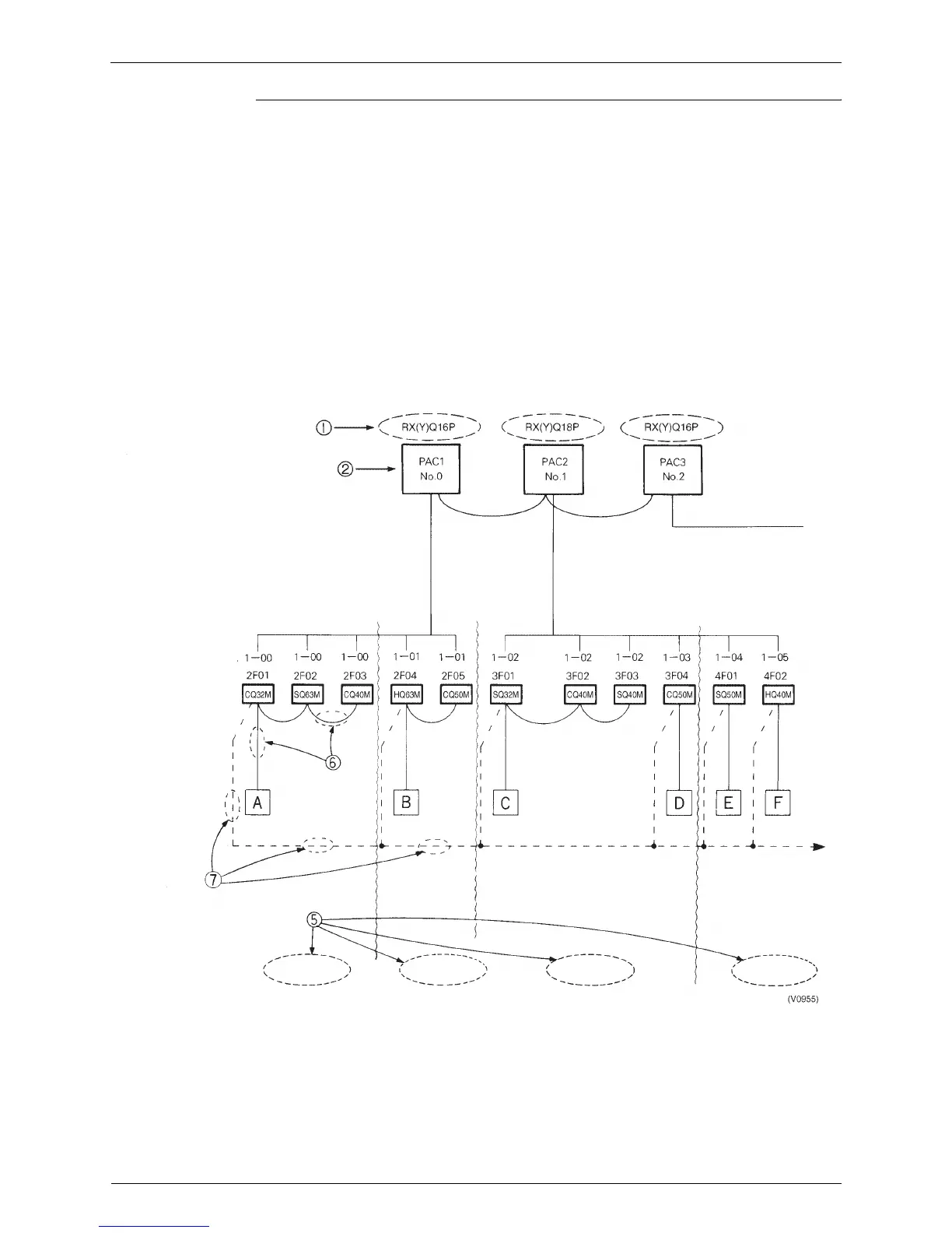
The following sequence should be followed in order to prepare control circuit diagrams in
accordance with the system list which has already been completed:
1 Diagrams should be prepared for each individual outdoor unit. The outdoor unit model
number should be inserted into the diagram. (RX(Y)Q16P)
2 Insert name of refrigerant system. (PAC1, PAC2)
3 Insert name of indoor unit. (FXCQ32M→CQ32M)
4 Insert system name of indoor unit.
5 Insert installation position. (Do this when demarcation is possible)
6 Insert remote control control wiring. (Group) Indicated by solid line. ........Solid line.
7 Insert centralized control wiring. ........Dotted line
8 Insert Group No. (G No. for each indoor unit with U No. 0)
The control circuit diagrams are now complete.
Example: Control circuit diagram
Example: Control circuit diagram
Centralized group No
쩻 System name
쩺 Model name
2nd floor office
2nd floor
reception room
3rd floor
design room
4th floor office
To central control panel