Do you have a question about the Daikin RXS09LVJU and is the answer not in the manual?
Crucial safety guidelines for performing repair work on the air conditioning system.
Important safety instructions and warnings for operating the air conditioning unit.
Detailed technical specifications for the FTXS Series indoor and outdoor units.
Detailed technical specifications for the FDXS Series indoor and outdoor units.
Comprehensive list of functions available for FTXS Series indoor and outdoor units.
Comprehensive list of functions available for FDXS Series indoor and outdoor units.
Overview of main operational functions including temperature and fan speed control.
Detailed explanations of control logic, mode hierarchy, and frequency control.
Instructions for operating FTXS Series units, including remote controller and modes.
Instructions for operating FDXS Series units, including remote controller and modes.
Explanation of remote controller parts, buttons, and display for FTXS Series.
Details on AUTO, DRY, COOL, HEAT, FAN, and other operational modes.
Procedures for adjusting airflow direction, rate, louvers, and 3D airflow.
Usage of COMFORT AIRFLOW, INTELLIGENT EYE, POWERFUL, ECONO, and Timer functions.
Guide to diagnosing issues using indoor and outdoor unit LED indicators.
Common symptoms, check items, and troubleshooting measures for operational issues.
Comprehensive list of error codes, their descriptions, and reference pages for diagnosis.
Step-by-step instructions for disassembling FTXS Series indoor units.
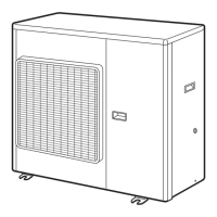
Procedures for removing outer panels, fan motor, electrical box, and PCBs.
Procedures for removing outer panels, fan motor, electrical box, and PCBs.
Procedures for removing outer panels, electrical box, PCBs, fan motor, and coils.
Procedures for removing outer panels, electrical box, PCBs, fan motor, and compressor.
Procedure for safely removing refrigerant before relocating or disposing of the unit.
Method to manually start cooling operation for testing purposes.
Steps for conducting trial operation to verify unit functionality after installation.
Settings for model type, temperature display, and special facility configurations.
Instructions for applying silicon grease to power transistor and diode bridge on outdoor unit PCB.
Diagrams illustrating refrigerant flow paths for indoor and outdoor units.
Electrical wiring diagrams for indoor and outdoor units.
| Heating Capacity | 3.2 kW |
|---|---|
| Indoor Unit Dimensions (W x H x D) | 800 x 295 x 223 mm |
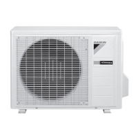
| Outdoor Unit Dimensions (W x H x D) | 780 x 550 x 285 mm |
| Type | Split System |
| Cooling Capacity | 2.6 kW |
| Cooling Capacity (BTU) | 9000 BTU |
| SEER | 5.4 |
| HSPF | 9.00 |
| Power Supply | 220-240 V, 50 Hz |
| Refrigerant | R32 |
| Weight (Outdoor Unit) | 28.0 kg |
| Outdoor Unit Noise Level | 49 dB |
| Indoor Unit Weight | 9.5 kg |
| Outdoor Unit Weight | 62 lb |