Do you have a question about the Daikin RXS24LVJU and is the answer not in the manual?
Overview of functions for FTXS and FDXS series air conditioning units.
Detailed list of functions available for the FTXS series indoor and outdoor units.
Detailed list of functions available for the FDXS series indoor and outdoor units.
Technical specifications for air conditioning units.
Technical data for FTXS series indoor and outdoor units.
Technical data for FDXS series indoor and outdoor units.
Connector and PCB layout for indoor units.
Connector and PCB layout for outdoor units.
Explanation of primary operational functions like temperature and fan speed control.
Details on the role and operation of thermistors in the system.
Technical specifications for various control mechanisms and modes.
Crucial safety guidelines and warnings for performing repair work on the unit.
Important safety instructions and warnings for end-users of the air conditioning system.
Information on system setup and initial operation after installation.
Detailed operation instructions for the FTXS series air conditioners.
Guide to the names and functions of parts on the FTXS series remote controller.
Detailed operation instructions for the FDXS series air conditioners.
Guide to the names and functions of parts on the FDXS series remote controller.
Diagnosing issues using LED indicators on indoor and outdoor units.
Common operational problems and their corresponding solutions.
Procedures for accessing and utilizing the service check function.
Guide to identifying and resolving errors based on error codes.
Detailed checks for various system components to diagnose faults.
Step-by-step guide for removing components of the FTXS09/12LVJU indoor unit.
Step-by-step guide for removing components of the FTXS15/18/24LVJU indoor unit.
Step-by-step guide for removing components of the FTXS30/36LVJU indoor unit.
Step-by-step guide for removing components of the RXS09/12LVJU outdoor unit.
Step-by-step guide for removing components of the RXS15/18LVJU outdoor unit.
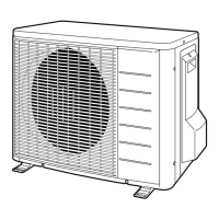
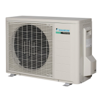
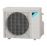
Procedure for removing the outer panels of the RXS24LVJU outdoor unit.
Procedure for removing the electrical box from the RXS24LVJU outdoor unit.
Procedure for removing the Printed Circuit Boards from the RXS24LVJU outdoor unit.
Procedure for removing the fan motor from the RXS24LVJU outdoor unit.
Procedure for removing coils and thermistors from the RXS24LVJU outdoor unit.
Procedure for removing the sound blankets from the RXS24LVJU outdoor unit.
Procedure for removing the compressor from the RXS24LVJU outdoor unit.
Procedure for removing outer panels for RKS30/36LVJU and RXS30/36LVJU outdoor units.
Procedure for removing the electrical box for RKS30/36LVJU and RXS30/36LVJU outdoor units.
Procedure for removing PCBs from RKS30/36LVJU and RXS30/36LVJU outdoor units.
Procedure for removing the fan motor from RKS30/36LVJU and RXS30/36LVJU outdoor units.
Procedure for removing coils and thermistors from RKS30/36LVJU and RXS30/36LVJU outdoor units.
Procedure for removing sound blankets from RKS30/36LVJU and RXS30/36LVJU outdoor units.
Procedure for removing the compressor from RKS30/36LVJU and RXS30/36LVJU outdoor units.
Procedure for pump down operation before relocating or disposing of the unit.
Instructions for initiating and managing the forced cooling operation mode.
Steps for performing trial operation to verify system functionality.
Configuration settings for the air conditioning system in the field.
Setting the heat pump or cooling-only model using DIP switch.
Procedure to switch between Fahrenheit and Celsius for temperature display.
Configuration for systems with two indoor units in one room.
Adjusting outdoor unit PCB settings for low outdoor temperature cooling.
Details on jumper functions for fan speed and power failure recovery.
Instructions for applying silicon grease to power transistor and diode bridge for heat dissipation.
Schematic diagrams illustrating the piping of the air conditioning system.
Piping diagrams specific to the indoor units.
Piping diagrams specific to the outdoor units.
Schematic diagrams illustrating the electrical wiring of the system.
Wiring diagrams specific to the indoor units.
Wiring diagrams specific to the outdoor units.
| Refrigerant | R-410A |
|---|---|
| Type | Split |
| Cooling Capacity | 24, 000 BTU/hr |
| Power Supply | 230V/50Hz |
| Indoor Unit Dimensions (W x H x D) | 800 x 290 x 230 mm |
| Outdoor Unit Dimensions (W x H x D) | 800 x 550 x 285 mm |