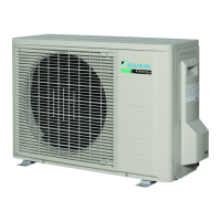
Do you have a question about the Daikin RXS25J2V1B and is the answer not in the manual?
Details detected malfunctions and their potential causes across system components.
Covers LED indicators, problem symptoms, and service check functions.
Interprets LED indicators on indoor and outdoor units for fault diagnosis.
Lists common operational problems and suggested troubleshooting steps.
Details specific service check functions, including the ARC452 Series.
Provides comprehensive troubleshooting for various error codes and system failures.
Addresses issues like PCB abnormalities and fan motor failures in the indoor unit.
Covers outdoor unit PCB issues, compressor overload, and fan lock errors.
Diagnoses signal transmission errors and voltage issues between units.
Details troubleshooting for compressor overload, lock, and sensor abnormalities.
Addresses input overcurrent, refrigerant shortage, and voltage detection issues.
Outlines specific checks for individual components like fan motors, valves, and thermistors.
Procedures for checking fan motor output and electronic expansion valve continuity.
Guides for testing four-way valve performance and thermistor resistance.
Step-by-step instructions for removing indoor unit parts like filters, panels, and PCBs.
Instructions for removing outer panels, fan motor, and related parts.
Instructions for removing outer panels, fan motor, and related parts.
Instructions for removing outer panels, discharge grille, and front panel.
Instructions for removing outer panels, discharge grille, and front panel.
| Model | RXS25J2V1B |
|---|---|
| Category | Air Conditioner |
| Type | Split System |
| Cooling Capacity | 2.5 kW |
| Heating Capacity | 3.2 kW |
| Energy Efficiency Ratio (EER) | 3.21 |
| Refrigerant | R-32 |
| Power Supply | 220-240 V, 50 Hz |
| Sound Power Level (Cooling) | 59 dB(A) |
| Sound Power Level (Heating) | 59 dB(A) |
| Sound Pressure Level (Cooling) | 38 dB |


