17 3P362438-1B English
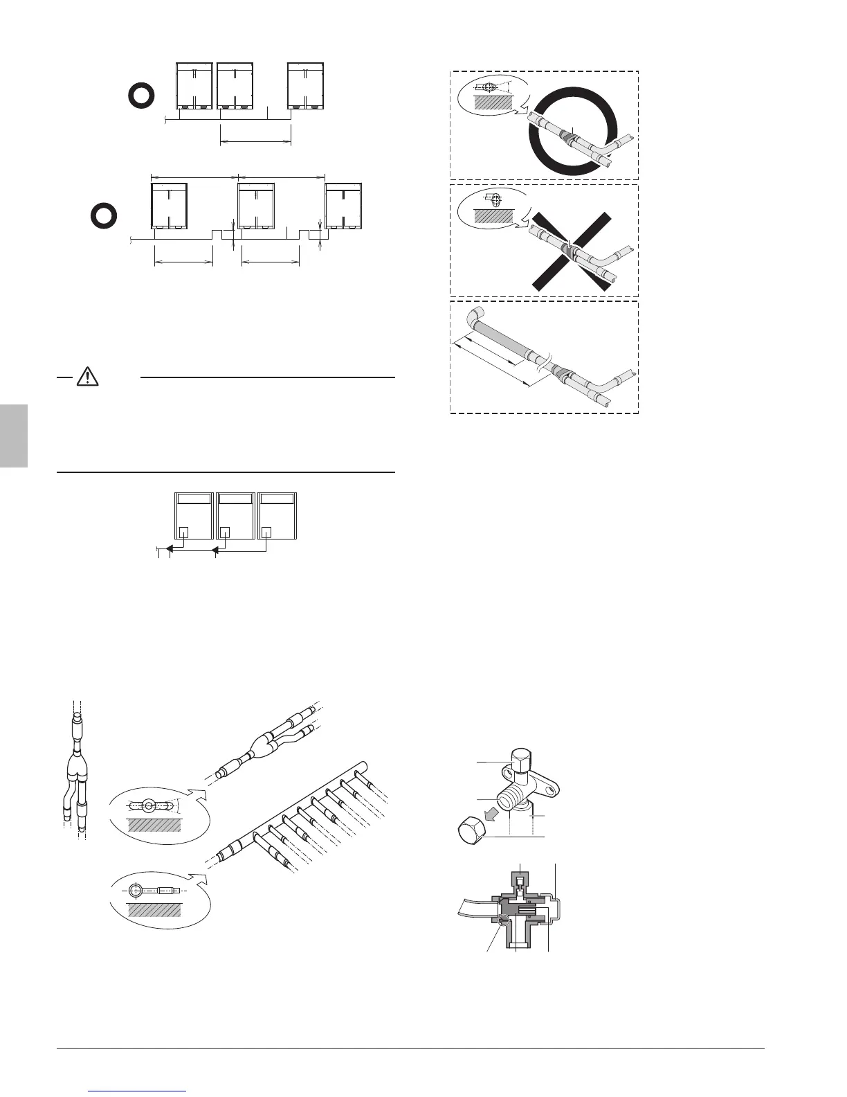
If≤6.5ft.(2m)
1
2
a
If>6.5ft.(2m)
1
a a
c
2
b b
c
1 To indoor unit
2 Piping between outdoor units
a ≤ 6.5 ft. (2 m)
b ≥ 8 in. (200 mm)
c > 6.5 ft. (2 m)
NOTE
There are restrictions on the refrigerant pipe connection order be-
tween outdoor units during installation in case of a multiple outdoor
unit system. Install according to following restrictions. The capacities
of outdoor units A, B and C must fulll the following restriction condi-
tions: A≥B≥C.
A B C
1 2 3
1 To indoor unit
2 Outdoor unit multi connecting piping kit (rst branch)
3 Outdoor unit multi connecting piping kit (second branch)
8.2.6. Branching the refrigerant piping
• For installation of the refrigerant branching kit, refer to the installa-
tion manual delivered with the kit.
A
B
±
3
0
°
1
1
1 Horizontal surface
1 Mount the refnet joint so that it branches either horizontally or
vertically.
2 Mount the refnet header so that it branches horizontally.
• Installation of the multi connection piping kit.
A
1
max
15
B
1
C
D
C > 4-3/4 in. (120 mm)
D > 19-11/16 in. (500 mm)
3 Install the joints horizontally, so that the caution label (1) attached
to the joint comes to the top.
- Do not tilt the joint more than 15° (see view A).
- Do not install the joint vertically (see view B).
4 Make sure that the total length of the piping connected to the joint
is absolute straight for more than 19-11/16 in. (500 mm). Only
if a straight eld piping of more than 4-3/4 in. (120 mm) is con-
nected, more than 19-11/16 in. (500 mm) of straight section can be
ensured.
5 Improper installation may lead to malfunction of the outdoor unit.
8.3. Guidelines for handling stop valve
8.3.1. Cautions on handling the stop valve
• Make sure to keep both stop valves open during operation.
• The gure below shows the name of each part required in handling
the stop valve.
• The stop valve is factory closed.
3
4
1
2
1 Service port and service port
cover
2 Stop valve
3 Field piping connection
4 Stop valve cover
345
1 Service port
2 Cap
3 Hexagon hole
4 Shaft
5 Seal
 Loading...