243P362438-1B English
For VRV IV heat pump system it is alternatively possible to make
several commissioning eld settings through a personal computer
interface (for this, option EKPCCAB* is required). The installer can
prepare the conguration (off-site) on PC and afterwards upload the
conguration to the system. How to connect the cable is described in
13.3. Connecting the PC congurator to the outdoor unit on
page25.
The contents of the actual settings is discussed and explained in 15.2.
Monitoring function and eld settings on page32.
13.1. Accessing the push buttons on the logic board
It is not required to open the complete control box to access the push
buttons on the logic board and read out the 7 segment display (s).
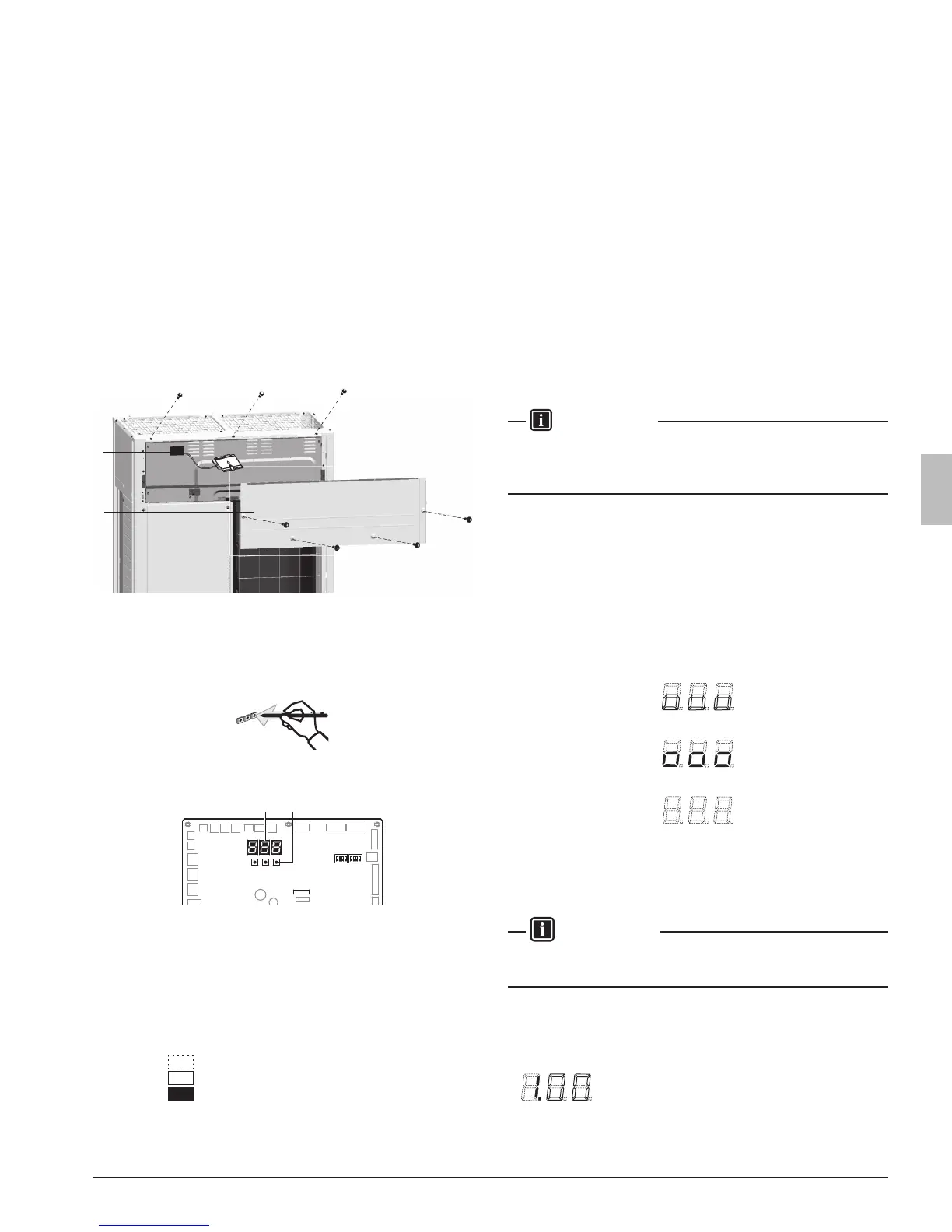
To access you can remove the front inspection door of the front panel
(see gure). Now you can open the inspection door of the control box
front panel (see gure). You can see 3 push buttons and 3 seven-
segment displays and DIP switches.
1
2
1 Front panel
2 Main printed circuit board with 3 seven-segment display
and 3 push buttons
Operate the switches and push buttons with an insulated stick (such
as a closed ballpoint pen) to avoid touching of live parts.
Location of the segment displays, buttons and DIP switches:
BS1 BS2
DS1 DS2
BS3
X27A
BS1 MODE for changing the set mode
BS2 SET for eld setting
BS3 RETURN for eld setting
DS1, DS2 DIP switches
1
7 segment displays (3×)
2 Push buttons
Segment display indications:
Off
Blinking
On
13.2. Operating the push buttons and DIP switches on
the logic board
13.2.1. Operating the push buttons
By operating the push buttons it is possible to:
• Perform special actions (automatic refrigerant charge, test run, etc).
• Perform eld settings (demand operation, low noise, etc).
Below procedure explains how to operate the push buttons to reach
the required mode in the menu, select the correct setting and modify
the value of the setting. This procedure can be used any time special
settings and regular eld setting are discussed in this manual (see
15.2. Monitoring function and eld settings on page32).
Setting denition: [A-B]=C; A=mode; B=setting; C=setting value. A, B
and C are numerical values for eld settings. Parameter C has to be
dened. It can be a chosen from a set (0, 1, 2, 3, 4, 5, …) or regarded
as an ON/OFF (1 or 0) depending on the contents. This is informed
when the eld setting is explained (see 15.2. Monitoring function and
eld settings on page32).
INFORMATION
During special operation (e.g., automatic refrigerant charging, test
run, etc.) or when an malfunction happened, information will contain
letters and numerical values.
Functions of the push button switches which are located on the
outdoorprintedcircuitboard(A1P)
Turn on the power supply of the outdoor unit and all indoor units.
When the communication between indoor units and outdoor unit (s) is
established and normal, the segment indication state will be as follows
(default situation when shipped from factory):
When turning on the power supply, the display ashes on and off. First
checks of the power supply are executed (1 – 2 min).
When no trouble occurs: lighted as indicated (8 – 10 min).
Ready for operation: blank display indication as indicated.
When above situation cannot be conrmed after 12 min, the malfunc-
tion code can be checked on the indoor unit user interface and the
outdoor unit segment display. Solve the malfunction code accordingly.
The communication wiring should be checked at rst.
INFORMATION
Be sure to turn the power on at least 6 hours before operation in order
to have power running to the crank case heater.
Accessing modes
BS1 is used to change the mode you want to access.
• Access mode 1
Push BS1 one time. Segment indication changes to:
 Loading...