Test Operation SiEN34-705
84 General Information
4.1.3 Check Operation
[Check Operation Procedure]
STEP1 Make the onsite setting as needed using the dip switches on the outdoor unit PC-board
(A1P) with the power off (See below instruction Note1)
STEP2 Close the EL. COMPO. BOX lid and all front panels except as the side of the EL.
COMPO. BOX and turn on the power to the outdoor unit and all connected indoor units.
(Be sure to turn the power on at least 6 hours before operation in order to have power
running to the crank case heater.)
STEP3 Check the LED display on the outdoor unit PC-board (A1P) is as shown in the table
below and transmission is normal.
LED display: 3...OFF, 4...ON, 5...Blinking
(*)How to distinguish the master unit, sub unit 1, and sub unit 2 in the multi system.
STEP4 Make the onsite settings as needed using the push button (BS1-BS5) on the outdoor
unit PC-board (A1P) with the power on. (See “4.4.2 Field Setting from Outdoor Unit.”)
STEP5 Perform the check operation following the Check Operation Method of the [Service
Precautions] label on the EL. COMPO. BOX lid. The system operation for about 40
minutes and automatically stops the check operation.
If the malfunction code is not displayed in the remote control after the system stop,
check operation is completed. Normal operation will be possible after 5 minutes. If the
malfunction code is displayed in the remote control, correct the malfunction following
[remote control displays malfunction code] and perform the check operation again.
Note1: Onsite Settings with the Power Off
If the COOL/HEAT selector was connected to the outdoor unit set the dip switch (DS1) on the
outdoor unit PC-board (A1P) to “ON” (it is set to “OFF” when shipped from the factory).
For the position of the dip switch (DS1), see the “Service Precautions” label (see at right) which
is attached to the EL. COMPO. BOX lid.
LED display
(Default status of shipped)
SERV.
MONI-
TOR
MODE
TEST/
HWL
C/H SELECTOR
L.N.O.P
DEMA-
ND
MULTI
IND
MASTE
R
SLAVE
HAP H1P H2P H3P H4P H5P H6P H7P H8P
Single system 533433333
Multi
system
(*)
Master unit 533433334
Sub unit 1 533333335
Sub unit 2 533333333
Method 1: By the H8P (MULTI) LED display
4 (ON): Master unit 5
(Blinking): Sub unit 1
3 (OFF): Sub unit 2
Method 2: By the transmission wiring to indoor unit
Transmission wiring is connected: Master unit
Transmission wiring is not connected : Sub unit 1 or Sub unit 2
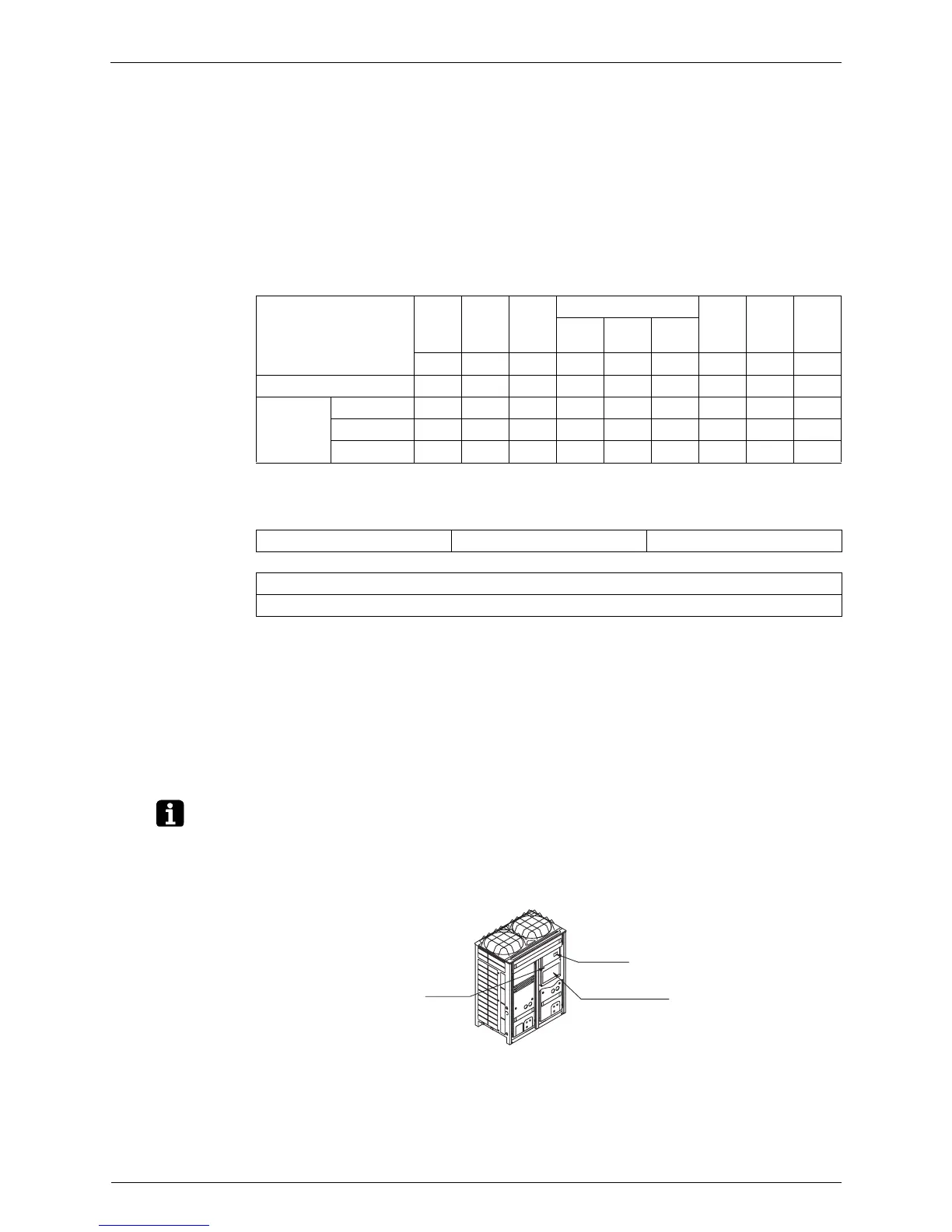
Inspection
door
[Service Precautions]
label
EL.COMPO.
BOX lid
 Loading...