Do you have a question about the Daikin Super Multi Plus E-Series RMXS140E8V1B and is the answer not in the manual?
Details various functions of the system models and their availability.
General overview of specifications for the system components.
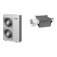
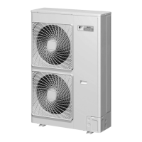
Detailed technical specifications for the outdoor unit models.
Detailed technical specifications for the BP unit.
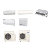
Detailed technical specifications for various indoor unit types.
Procedures for configuring system parameters in the field.
Field settings specific to the outdoor unit.
Field settings for RA indoor unit series.
Field settings for SA indoor unit series.
Wiring diagrams for the outdoor unit components.
Specific wiring details for RMXS outdoor units.
Wiring diagrams for the BP unit components.
Specific wiring details for BPMKS BP units.
Wiring diagrams for indoor unit components.
Wiring diagrams for wall-mounted indoor units.
Wiring diagrams for floor-standing indoor units.
Wiring diagrams for floor/ceiling suspended indoor units.
Wiring diagrams for duct-connected indoor units.
Wiring diagrams for ceiling-mounted cassette indoor units.
Wiring diagrams for ceiling-mounted built-in indoor units.
Wiring diagrams for ceiling suspended indoor units.
Wiring diagrams for remote controller components.
Wiring diagrams for wired remote controllers.
Wiring diagrams for wireless remote controllers.
Overview of the system's various operating modes.
Fundamental control mechanisms for system operation.
Details of normal operational parameters and actuator functions.
Explains PI control for compressor capacity adjustment.
PI control for electronic expansion valves for evaporator control.
Controls fan speed based on pressure for cooling operations.
Covers special operational controls like startup and oil return.
Manages compressor startup and pressure equalization.
Mechanism for recovering oil to the compressor.
Process to remove frost from the outdoor unit heat exchanger.
Collects refrigerant in heat exchangers during shutdown.
Prevents frequent power cycling and equalizes pressure.
Details actuator status when the system is down.
Safety controls for preventing damage due to abnormal conditions.
Protects against abnormal high pressure.
Protects against transient low pressure.
Protects compressor from high discharge pipe temperature.
Prevents tripping due to overcurrent or fin temperature rise.
Prevents indoor heat exchanger freezing.
Prevents dew condensation on the indoor unit.
Additional control functions not covered elsewhere.
Saves power consumption by limiting capacity.
Prohibits heating operation above a certain outdoor temperature.
Control functions specific to the BP unit.
Converts BP unit signals to capacity commands.
Controls electronic expansion valves for the BP unit.
Ensures refrigerant distribution in cooling mode.
Ensures refrigerant distribution in heating mode.
Controls refrigerant distribution to prevent pressure issues.
Control functions for RA indoor units.
Manages temperature based on sensor readings.
Controls initial operation of functional parts.
Adjusts airflow direction for user comfort.
Controls fan speed across multiple steps.
Removes humidity while maintaining temperature.
Automatically determines cooling or heating mode.
Controls operation based on temperature difference.
Adjusts target temperature slightly for comfortable sleep.
Reduces operating current and power consumption.
Records and starts favorite temperature/airflow settings.
Detects people in two areas and adjusts airflow.
Uses motion sensor for energy saving.
Maximizes cooling/heating by increasing fan speed and compressor frequency.
Miscellaneous functions like hot start.
Procedures for initial test operation after installation.
Steps for conducting test operations.
Behavior of the unit when power is first applied.
Diagram of the outdoor unit's PCB layout.
Procedures for BP unit address management.
Trial operation procedures for RA indoor units.
Test operation procedures for SA indoor units.
Settings to be configured in the field.
Field settings specific to the outdoor unit.
Field settings for RA indoor unit series.
Field settings for SA indoor unit series.
Overview of the system's configuration and initial handling.
Information and points to note regarding the outdoor unit.
Specific details for RMXS series outdoor units.
Information regarding RA indoor units.
Operation details for FTXG-J/CTXG-J series with ARC466A1.
Operation details for FTXS-G/FVXS series with ARC452A1/A3.
Operation details for FTXG-E/CTXG-E/FTXS-F/FLXS/FDXS series.
Operation details for SA indoor units.
Operation details for BRC1D528 remote controller.
Operation details for BRC1E51A7 remote controller.
Operation details for BRC7E530W/BRC7F532F/BRC7EA63W controllers.
Troubleshooting based on LED indicators on PCBs.
Troubleshooting for outdoor unit LEDs.
Troubleshooting for BP unit LEDs.
Troubleshooting for indoor unit LEDs.
Procedures for performing service checks.
Service checks for RA indoor unit series.
Service checks for SA indoor unit series.
List and explanation of error codes and descriptions.
General troubleshooting guide for RA indoor units.
Troubleshooting abnormal indoor unit PCB.
Troubleshooting freeze-up and peak-cut controls.
Troubleshooting fan motor issues.
Troubleshooting thermistor issues in indoor units.
Troubleshooting front panel mechanism faults.
General checks for RA indoor units.
General troubleshooting guide for SA indoor units.
Troubleshooting abnormal indoor unit PCB.
Troubleshooting drain system abnormalities.
Troubleshooting fan motor issues for FHQ series.
Troubleshooting swing motor lock for FHQ series.
Troubleshooting drain system abnormalities.
Troubleshooting R2T thermistor abnormality.
Troubleshooting R3T thermistor abnormality.
Troubleshooting R1T thermistor abnormality.
Troubleshooting remote controller thermistor abnormality.
Troubleshooting remote to indoor unit communication errors.
Troubleshooting main/sub remote controller communication errors.
Troubleshooting field setting switch issues.
General troubleshooting guide for BP units.
Troubleshooting electronic expansion valve abnormalities.
Troubleshooting BP unit PCB issues.
Troubleshooting BP unit thermistor abnormalities.
Troubleshooting indoor to BP unit communication errors.
Troubleshooting outdoor to BP unit communication errors.
General checks for BP units.
General troubleshooting guide for outdoor units.
Troubleshooting outdoor unit PCB issues.
Troubleshooting high pressure switch actuation.
Troubleshooting low pressure sensor actuation.
Troubleshooting compressor motor lock issues.
Troubleshooting outdoor fan motor issues.
Troubleshooting EE valve moving part abnormalities.
Troubleshooting discharge pipe temperature issues.
Troubleshooting for refrigerant overcharge.
Procedures for disassembling the outdoor unit.
Steps to remove outer panels.
Steps to remove PCBs and electrical components.
Steps to remove outdoor fans and motors.
Steps to remove thermistors.
Steps to remove electronic expansion valves and peripherals.
Steps to remove the four-way valve.
Steps to remove the compressor.
Procedures for disassembling the BP unit.
Steps to remove the BP unit PCB assembly.
Steps to remove electronic expansion valve coils.
Visual representations of the system's piping.
Piping diagrams for the outdoor unit.
Piping diagrams for the BP unit.
Piping diagrams for various indoor unit types.
Visual representations of the system's wiring.
Wiring diagrams for the outdoor unit.
Wiring diagrams for the BP unit.
Wiring diagrams for various indoor unit types.
| Series | Super Multi Plus E-Series |
|---|---|
| Model | RMXS140E8V1B |
| Category | Air Conditioner |
| Brand | Daikin |
| Cooling Capacity | 14.0 kW |
| Heating Capacity | 16.0 kW |
| Seasonal Energy Efficiency Ratio (SEER) | 6.1 |
| Power Source | Electric |
| Power Supply | 380-415V, 3 Phase |
| Indoor Unit Compatibility | Compatible with various Daikin indoor units |
| Type | Multi-Split System |
| Refrigerant | R32 |