Do you have a question about the Daikin Super Multi NX B series and is the answer not in the manual?
Provides an overview of the manual and general safety information.
Details functions available for cooling-only models across various categories.
Details functions available for heat pump models across various categories.
Technical specifications for indoor units designed for cooling-only operation.
Technical specifications for outdoor units designed for cooling-only operation.
Technical specifications for indoor units designed for heat pump operation.
Technical specifications for outdoor units designed for heat pump operation.
Connector wiring diagram for wall-mounted indoor units of 25/35 class.
Connector wiring diagram for wall-mounted indoor units of 50/60/71 class.
Connector wiring diagram for floor/ceiling suspended dual type indoor units.
Connector wiring diagram for duct-connected indoor units.
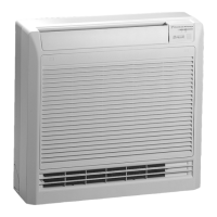
Connector wiring diagram for floor-standing indoor units.
Connector wiring diagram for outdoor units.
Details the main functions of the air conditioner system and their operational principles.
Explains the function of key structural components within the air conditioner system.
Details the control logic and specifications for various operating modes and functions.
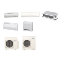
Overview of system configuration, operation instructions, and important instructions.
Provides instructions, manual contents by models, safety precautions, and part identification.
Important cautions to be observed before performing any diagnostic procedures.
Lists common symptoms and their corresponding measures for diagnosing and resolving issues.
Explains how to use the service check function to diagnose system codes and identify faults.
Provides a list of error codes displayed on the remote controller and their descriptions.
Detailed troubleshooting steps for various indoor and outdoor unit issues.
Step-by-step instructions for removing outer panels and components from outdoor units (80/90 class).
Step-by-step instructions for removing outer panels and components from outdoor units (52/58/68/75 class).
Procedure for performing test runs using the remote controller in cooling or heating modes.
Explains jumper settings for two units in one room and PCB jumper functions like power failure recovery.
Contains piping diagrams for indoor and outdoor units, illustrating refrigerant flow and connections.
Provides wiring diagrams for indoor and outdoor units, detailing electrical connections and components.
Flow chart or diagram related to the anti-icing function in multiple rooms.
Diagram or flow chart illustrating automatic control of air flow.
Diagram or flow chart explaining the automatic operation mode.
Diagram or flow chart illustrating the auto-swing function for airflow direction.
Flow chart for checking capacitor voltage as part of troubleshooting.
Troubleshooting flow chart for compressor lock issues.
Troubleshooting flow chart for compressor overload (OL activation).
Diagram or flow chart related to compressor protection functions.
Diagram or flow chart illustrating the pipe condensation prevention function.
Wiring or schematic diagram for the control PCB.
Diagram or flow chart for setting the cooling/heating mode lock.
Troubleshooting flow chart for CT or related abnormalities.
Troubleshooting flow chart for DC fan lock.
Flow chart or diagram illustrating the defrost control process.
Diagram or flow chart for discharge pipe temperature control.
Diagram or flow chart for discharge pipe temperature control.
Flow chart for performing a discharge pressure check.
Wiring or schematic diagram for the display PCB.
Troubleshooting flow chart for electrical box temperature rise.
Flow chart for checking the electronic expansion valve.
Diagram showing the removal of the electronic expansion valve coil.
Diagram or flow chart illustrating electronic expansion valve control.
List of error codes and descriptions of faults for remote controller indications.
Troubleshooting flow chart for error code F3 (Discharge Pipe Temperature Control).
Diagram or flow chart illustrating fan control logic.
Diagram or flow chart related to the fan motor.
Troubleshooting flow chart for DC fan motor abnormalities.
Flow chart for checking the fan motor connector output.
Diagram or flow chart illustrating fan speed control.
Flow chart illustrating the forced operation mode for service and installation.
Troubleshooting flow chart for four way valve abnormalities.
Diagram or flow chart for four way valve operation compensation.
Flow chart for checking the four way valve performance.
Flow chart related to freeze-up protection control.
Troubleshooting flow chart for freeze-up protection and high pressure control.
Flow chart illustrating the frequency control logic.
Diagram explaining the principle of frequency control for the compressor.
List of available functions for the air conditioner models.
Diagram or flow chart for gas pipe isothermal control during cooling.
Troubleshooting flow chart for gas pipe thermistor issues.
Flow chart illustrating the heating peak-cut control.
Diagram or flow chart explaining the home leave operation.
Diagram or flow chart illustrating the hot start function.
Troubleshooting flow chart for indoor heat exchanger thermistor.
Troubleshooting flow chart for indoor liquid pipe thermistor.
| Brand | Daikin |
|---|---|
| Model | Super Multi NX B series |
| Category | Air Conditioner |
| Language | English |