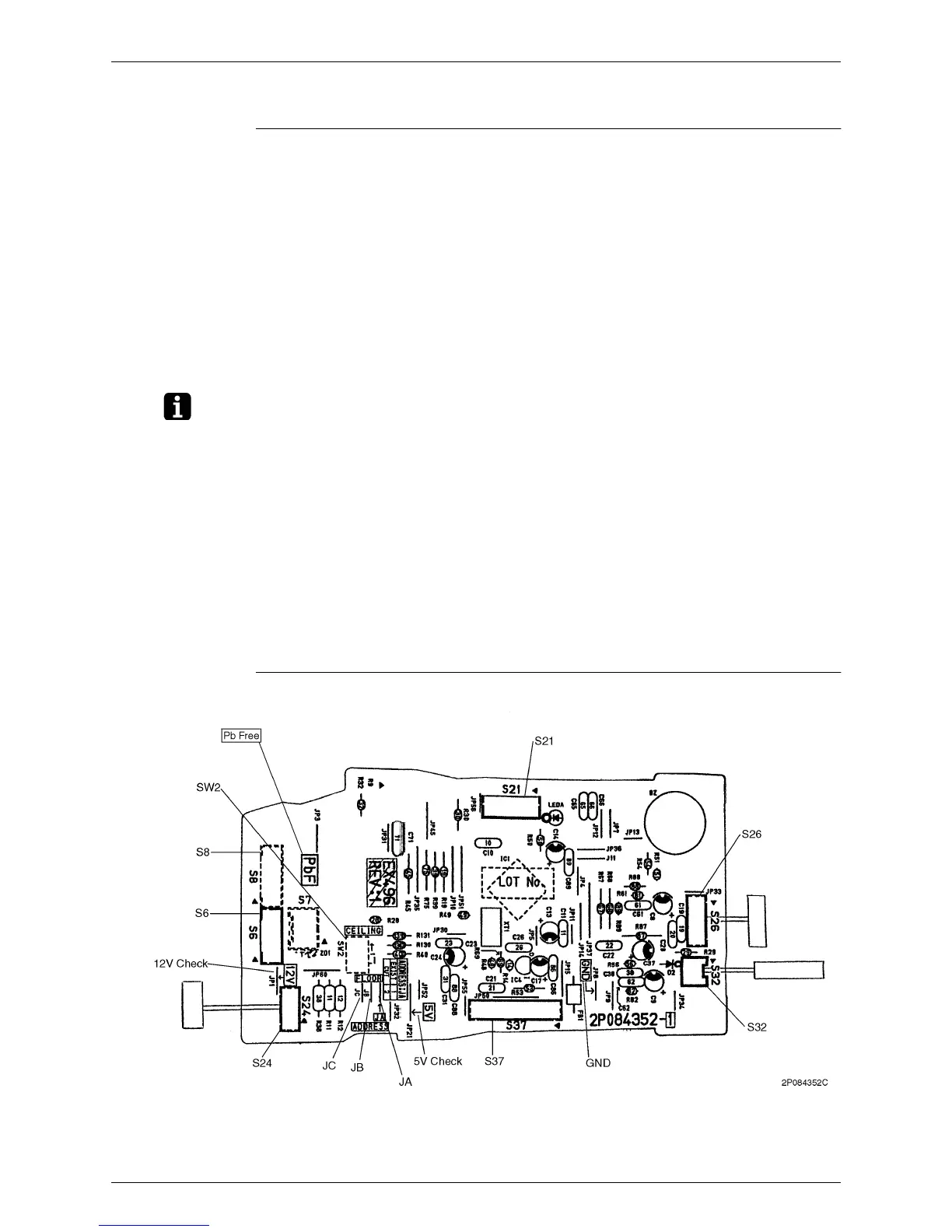
Si12-308 Printed Circuit Board Connector Wiring Diagram
Printed Circuit Board Connector Wiring Diagram 67
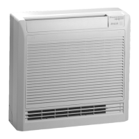
1.3 Floor / Ceiling Suspended Dual Type
Connectors
Note: Other designations
Control PCB (PCB 1)
1) S6 Connector for Swing Motor (Horizontal Swing)
2) S7 Connector for Fan Motor
3) S8 Connector for Swing Motor (Vertical Swing)
4) S21 Connector for Centralized Control
5) S24 Connector for Display PCB
6) S25, S27, S36 Connector for Control PCB
7) S26 Connector for Signal Receiver PCB
8) S31 Connector for Room Temp. Thermistor
9) S32 Connector for Heat Exchanger Thermistor
10) S37 Connector for Power Supply PCB
1) V1 Varistor
2) JA Address setting jumper
JB Fan speed setting when compressor is OFF on thermostat
JC Power failure recovery function
∗
Refer to page 259 for detail.
3) SW1 Operation Switch
4) SW2 Select Switch Ceiling or Floor
5) LED1 (GRN) LED for operation
6) LED2 (YLW) LED for timer
7) LED3 (RED) LED for intelligent eye
 Loading...