Si12-308 Printed Circuit Board Connector Wiring Diagram
Printed Circuit Board Connector Wiring Diagram 69
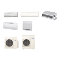
1.4 Duct Connected Type
Connectors
Note: Other designations
Control PCB Detail (PCB 1)
Refer to PCB (1) Control on P64.
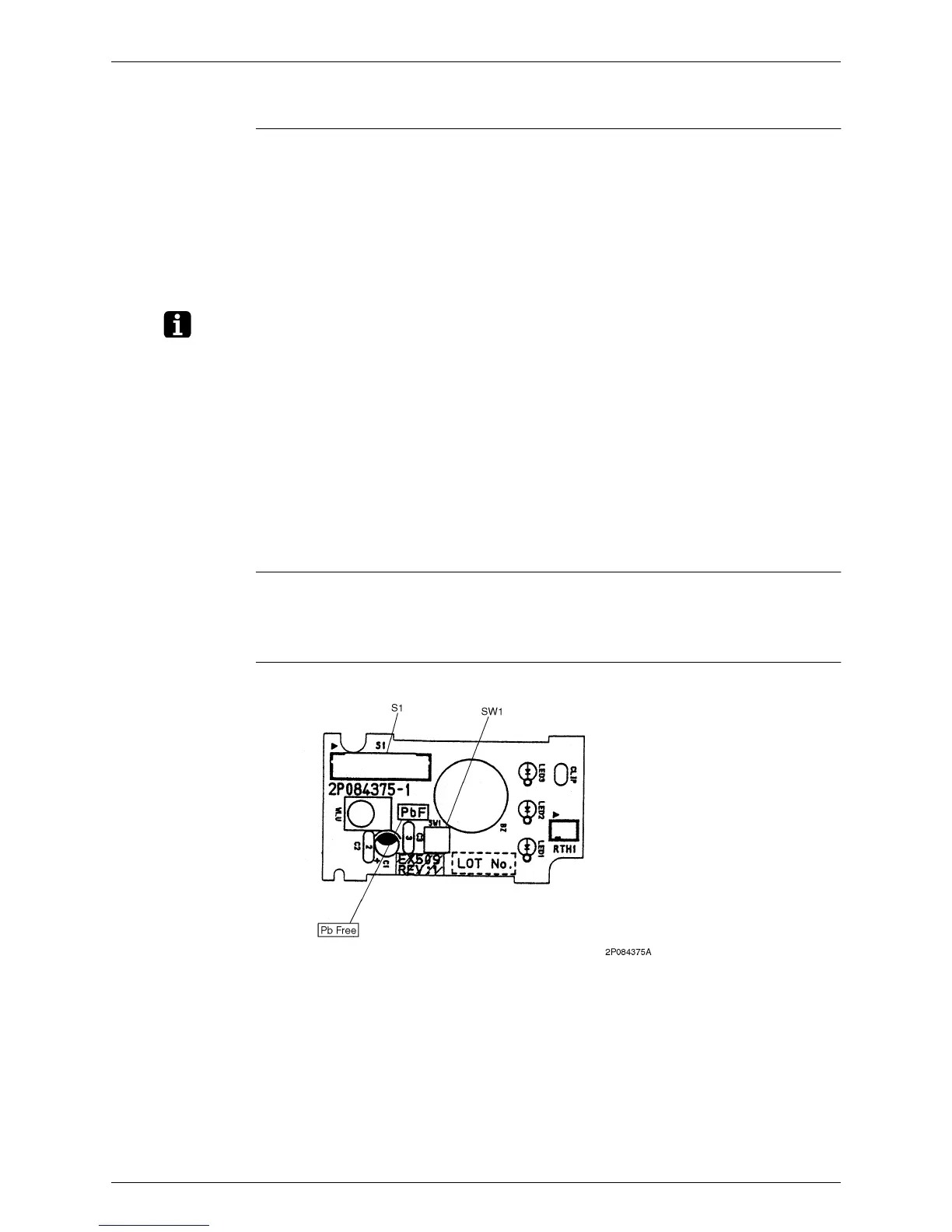
Display PCB Detail (PCB 2)
1) S1 (on PCB 1) Connector for fan motor
2) S1 (on PCB 2) Connector for control PCB
3) S7 Connector for fan motor
4) S21 Connector for centralized control to 5 rooms
5) S26 Connector for display PCB
6) S32 Connector for room temp / Heat exchanger thermistor
1) V1 Varistor
2) JA Address setting jumper
JB Fan speed setting when compressor is OFF on thermostat
JC Power failure recovery function
∗
Refer to page 259 for more detail.
3) SW1 OPERATION SWITCH
4) LED1 (GRN) LED for operation
5) LED2 (YLW) LED for timer
6) LED3 (RED) LED for intelligent eye
 Loading...