Do you have a question about the Daikin Super Multi Plus E-Series RMXS160E8V1B and is the answer not in the manual?
Details the various functions available for different indoor and outdoor units.
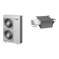
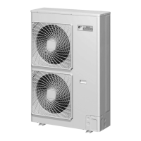
Provides detailed specifications for outdoor units including capacity, power, dimensions, and sound.
Lists specifications for BP units, including connectable units, dimensions, weight, and piping.
Details specifications for different indoor unit types like Wall Mounted, Floor Standing, etc.
Diagram showing PCB layout, connectors, and components for the outdoor unit.
Illustrates the PCB layout, connectors, and components for the BP unit.
Details the PCB layout for various indoor unit types, including connectors and components.
Diagrams showing the PCB layout for wired and wireless remote controllers.
Lists and describes the function of each component in the refrigerant circuit.
Diagram and description of the refrigerant flow and components for the BP unit.
Illustrates refrigerant flow during Cooling, Heating, and Oil Return operations.
Details normal operation controls for compressor, fan, expansion valves, and bypass valve.
Explains controls like startup, oil return, defrosting, pump-down, and stopping operations.
Details protection mechanisms for high pressure, low pressure, temperature limits, and inverter.
Describes temperature, airflow, and operational controls for RA model indoor units.
Explains drain pump, thermostat sensor, and freeze prevention controls for SA model indoor units.
Outlines the procedure for initial test operation, including checks and power-on steps.
Details field settings made via DIP switches on the outdoor unit PCB.
Explains model type and address setting procedures for RA indoor units.
Details field settings for SA indoor units, including low noise and demand operations.
Provides guidance on operating and handling the air conditioner after installation.
Explains operational points for the outdoor unit, including comfort and noise considerations.
Details the names of parts and operation procedures for RA indoor units.
Describes names and functions of switches, icons, and operation modes for SA indoor units.
Guides troubleshooting by interpreting LED indications on the main and service PCBs.
Details service check methods using the remote controller to diagnose errors and status.
Lists error codes, their descriptions, and reference pages for detailed troubleshooting.
Provides troubleshooting steps for common abnormalities in RA indoor units like PCB, fan motor, and thermistors.
Details troubleshooting for SA indoor units, including PCB, drain system, fan motor, and thermistor issues.
Covers troubleshooting for BP unit abnormalities like expansion valve, PCB, and thermistors.
Addresses outdoor unit issues like PCB abnormalities, sensor errors, compressor, and fan motor problems.
Step-by-step instructions for removing outer panels, PCBs, fans, motors, and other components.
Instructions for removing the PCB assembly and electronic expansion valve coils from the BP unit.
Diagrams illustrating the piping connections for Outdoor, BP, and Indoor units.
Diagrams showing the wiring connections for Outdoor, BP, and Indoor units.
| Series | Super Multi Plus E-Series |
|---|---|
| Model | RMXS160E8V1B |
| Category | Air Conditioner |
| Brand | Daikin |
| Cooling Capacity | 16.0 kW |
| Heating Capacity | 18.0 kW |
| Refrigerant | R-32 |
| Power Source | Electric |
| Power Supply | 380-415V, 3 Ph, 50Hz |
| Indoor Unit Compatibility | Various Models |
| Type | Multi-Split System Outdoor Unit |