Do you have a question about the Daikin Super Multi Plus E-Series FCQ60C7VEB and is the answer not in the manual?
Lists the operational functions available for the system.
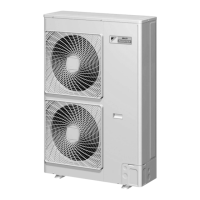
Provides detailed specifications for outdoor units.
Lists the specifications for the BP unit.
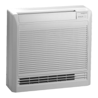
Details specifications for various indoor unit types.
Shows the PCB layout and connector assignments for outdoor units.
Details the PCB layout and connector assignments for BP units.
Provides PCB layouts and connector assignments for indoor units.
Illustrates the wiring diagrams for wired and wireless remote controllers.
Details refrigerant circuit components and their functions.
Illustrates the physical layout of key components in the outdoor unit.
Diagrams showing refrigerant flow during cooling and heating operations.
Outlines the system's operational modes and transitions.
Explains normal operation controls for compressor and fans.
Details special controls like startup and oil return.
Explains protection mechanisms against various fault conditions.
Covers control functions specific to RA indoor units.
Details control functions specific to SA indoor units.
Provides procedures for initial test operations after installation.
Explains configuration settings via dip switches and remote controller.
Explains basic system operation and handling for users.
Details operational points and customer awareness for the outdoor unit.
Describes names of parts and basic operation for RA indoor units.
Explains names of parts and basic operation for SA indoor units.
Explains how to interpret LED indicators on PCBs for fault diagnosis.
Details procedures for performing service checks using the remote controller.
Lists error codes, descriptions, and corresponding reference pages.
Provides specific troubleshooting steps for RA indoor units.
Offers troubleshooting guidance for SA indoor units.
Details troubleshooting steps for the BP unit.
Covers troubleshooting common issues with outdoor units.
Details procedures for removing outer panels and components from the outdoor unit.
Explains the procedure for removing the PCB assembly from the BP unit.
Illustrates refrigerant piping configurations for various unit types.
Shows electrical wiring diagrams for outdoor, BP, and indoor units.
| Model | FCQ60C7VEB |
|---|---|
| Category | Air Conditioner |
| Series | Super Multi Plus E-Series |
| Cooling Capacity | 6.0 kW |
| Power Supply | 220-240 V, 50 Hz |
| Refrigerant | R410A |