Do you have a question about the Daikin Super Multi Plus E-Series CTXG50EV1BW and is the answer not in the manual?
Lists the various functions available for the air conditioning system.
Contains detailed specifications for different components of the system.
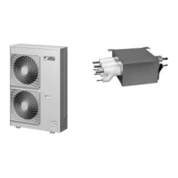
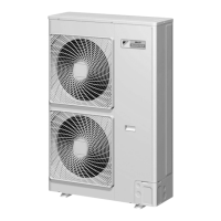
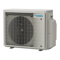
Provides detailed technical specifications for the outdoor units.
Details the specifications for the BP (Booster) unit.
Lists specifications for various types of indoor units.
Details specifications for remote controllers.
Wiring diagrams for outdoor unit PCBs and connectors.
Wiring diagrams for BP unit PCBs and connectors.
Wiring diagrams for various types of indoor unit PCBs and connectors.
Wiring diagrams for remote controllers.
Explains the overall refrigerant circuit for the system.
Details the refrigerant circuit within the outdoor unit.
Details the refrigerant circuit within the BP unit.
Identifies and locates key functional components.
Layout of functional parts in the outdoor unit.
Illustrates refrigerant flow during different operational modes.
Shows refrigerant flow during cooling operation.
Shows refrigerant flow during heating operation.
Illustrates refrigerant flow during cooling oil return.
Illustrates refrigerant flow during heating oil return and defrost.
Describes the different operating modes of the air conditioner.
Explains fundamental control principles for normal operation.
Details normal operation parameters for cooling and heating.
Explains the proportional-integral control logic for compressor capacity.
Details PI control for electronic expansion valves.
Explains how fan speed is controlled during cooling operation.
Covers special control functions like startup and oil return.
Details controls implemented during system startup.
Explains the process of returning oil to the compressor.
Describes the operation sequence for defrosting the outdoor unit heat exchanger.
Explains the operation to collect refrigerant when the compressor is down.
Describes the standby state after a restart.
Details how operation is stopped.
Details various protection mechanisms to prevent system damage.
Describes controls to prevent high pressure issues.
Explains controls to prevent low pressure issues.
Details protection against high discharge pipe temperatures.
Covers protection against inverter overcurrent and fin temperature.
Explains controls to prevent indoor unit freezing.
Details controls to prevent dew condensation on indoor units.
Covers miscellaneous control functions.
Explains control to save power consumption by limiting capacity.
Describes conditions under which heating operation is prohibited.
Specific controls for the BP unit.
How BP unit signals are converted to capacity commands.
Control logic for the BP unit's electronic expansion valve.
Superheat control logic for cooling operation.
Subcooling control logic for heating operation.
Control for maintaining heat exchanger temperature during heating.
Detailed controls for RA model indoor units.
How temperature is controlled in RA indoor units.
Control sequence for starting operations.
How airflow direction is managed.
Details on how fan speed is controlled.
Explanation of the program dry operation mode.
How automatic cooling/heating mode selection works.
Control based on thermostat settings.
Mode for comfortable sleeping conditions.
Operation mode to reduce power consumption.
Function to record and recall preferred settings.
Operation using sensors to detect human presence in two areas.
Operation using motion sensors for energy saving.
Operation for maximizing cooling/heating capacity.
Covers additional operational features.
Specific controls for SA model indoor units.
Details on drain pump operation and float switch behavior.
Explains the use of the remote controller's thermostat sensor.
Controls to prevent indoor unit freezing.
Control to prevent cold air blast during heating startup.
Procedures for initial system testing after installation.
Steps for conducting the test operation.
Behavior of the unit upon initial power activation.
Diagram showing the layout of the outdoor unit's Printed Circuit Board.
Procedures related to the BP unit, including address management.
Test operation procedures for specific RA indoor unit series.
Test operation procedures for specific SA indoor unit series.
Procedures for configuring system settings in the field.
Field settings for the outdoor unit, including DIP switches.
Field settings for specific RA indoor unit series.
Field settings for specific SA indoor unit series.
Overview of system setup and user handling recommendations.
Information related to the outdoor unit's operation.
Specific operational points for the RMXS series outdoor units.
Information related to RA indoor units.
Details on RA indoor units using the ARC466A1 remote controller.
Details on RA indoor units using the ARC452A1, A3 remote controllers.
Details on RA indoor units using ARC433 series remote controllers.
Information related to SA indoor units.
Details on SA indoor units using the BRC1D528 remote controller.
Details on SA indoor units using the BRC1E51A7 remote controller.
Details on SA indoor units using specific BRC7 series remote controllers.
Troubleshooting guide based on LED indicators on PCBs.
LED troubleshooting for the outdoor unit.
LED troubleshooting for the BP unit.
LED troubleshooting for indoor units.
Procedures for performing service checks on the system.
Service check procedures for specific RA indoor unit series.
Service check procedures for specific SA indoor unit series.
Lists and explains all error codes and their descriptions.
Specific troubleshooting steps for RA indoor units.
Troubleshooting steps for abnormal indoor unit PCBs.
Troubleshooting for freeze-up and heating peak-cut controls.
Troubleshooting for fan motor issues.
Troubleshooting for indoor unit thermistor issues.
Troubleshooting for front panel operation faults.
General checks for RA indoor units.
Specific troubleshooting steps for SA indoor units.
Troubleshooting for abnormal SA indoor unit PCBs.
Troubleshooting for drain water level issues.
Troubleshooting for fan motor issues in FHQ series.
Troubleshooting for swing motor lock issues in FHQ series.
Troubleshooting for drain system abnormalities.
Troubleshooting for indoor liquid pipe thermistor issues.
Troubleshooting for indoor heat exchanger thermistor issues.
Troubleshooting for suction air thermistor issues.
Troubleshooting for remote controller thermistor issues.
Troubleshooting transmission errors between remote and indoor units.
Troubleshooting transmission errors between main and sub remote controllers.
Troubleshooting for field setting switch abnormalities.
Specific troubleshooting steps for the BP unit.
Troubleshooting for electronic expansion valve issues.
Troubleshooting for abnormal BP unit PCBs.
Troubleshooting for BP unit thermistor issues.
Troubleshooting transmission errors between indoor and BP units.
Troubleshooting transmission errors between outdoor and BP units.
General checks for the BP unit.
Specific troubleshooting steps for outdoor units.
Troubleshooting for abnormal outdoor unit PCBs.
Troubleshooting for high pressure switch actuation.
Troubleshooting for low pressure sensor actuation.
Troubleshooting for compressor motor lock issues.
Troubleshooting for outdoor fan motor issues.
Troubleshooting for electronic expansion valve moving part issues.
Troubleshooting for discharge pipe temperature abnormalities.
Troubleshooting for issues related to refrigerant overcharge.
Troubleshooting for outdoor temperature thermistor issues.
Troubleshooting for discharge pipe thermistor issues.
Troubleshooting for suction pipe thermistor issues.
Troubleshooting for outdoor heat exchanger thermistor issues.
Troubleshooting for outdoor liquid pipe thermistor issues.
Troubleshooting for subcooling heat exchanger gas pipe thermistor issues.
Troubleshooting for high pressure sensor issues.
Troubleshooting for low pressure sensor issues.
Troubleshooting for abnormal outdoor unit PCBs.
Troubleshooting for radiation fin temperature rise issues.
Troubleshooting for inverter compressor abnormalities.
Troubleshooting for inverter current abnormalities.
Troubleshooting for compressor start-up errors.
Troubleshooting for high voltage issues in the main inverter circuit.
Troubleshooting for radiation fin thermistor abnormalities.
Troubleshooting low pressure drop issues.
Troubleshooting power supply issues.
Steps to take when check operation cannot be performed.
Troubleshooting transmission errors between remote and indoor units.
Troubleshooting transmission errors between main and sub remote controllers.
Troubleshooting transmission errors within the same system.
Troubleshooting for issues related to an excessive number of indoor units.
Troubleshooting address duplication issues with central remote controllers.
Troubleshooting transmission errors with centralized controllers.
Troubleshooting when the system settings are not configured.
Troubleshooting system abnormalities or undefined refrigerant addresses.
General checks for the outdoor unit.
Data on thermistor resistance relative to temperature.
Information regarding pressure sensors.
Procedure for replacing inverter power transistors.
Procedures for disassembling the outdoor unit.
Step-by-step guide to removing outer panels.
Steps for removing PCBs and electrical components.
Procedures for removing outdoor fans and motors.
Steps for removing thermistors.
Procedures for removing expansion valves and peripherals.
Steps for removing the four-way valve.
Procedure for removing the compressor.
Procedures for disassembling the BP unit.
Steps for removing the BP unit's PCB assembly.
Procedures for removing electronic expansion valve coils.
Diagrams illustrating refrigerant piping connections.
Piping diagrams specific to the outdoor unit.
Piping diagrams specific to the BP unit.
Piping diagrams specific to indoor units.
Diagrams illustrating electrical wiring connections.
Wiring diagrams specific to the outdoor unit.
Wiring diagrams specific to the BP unit.
Wiring diagrams specific to indoor units.
| Brand | Daikin |
|---|---|
| Model | Super Multi Plus E-Series CTXG50EV1BW |
| Category | Air Conditioner |
| Language | English |