SiBE18-821_C
Table of Contents ii
1. Introduction ........................................................................................... vii
1.1 Safety Cautions ...................................................................................... vii
1.2 Used Icons .............................................................................................. xi
Part 1 List of Functions ................................................................ 1
1. Functions.................................................................................................2
Part 2 Specifications .................................................................. 10
1. Specifications ........................................................................................11
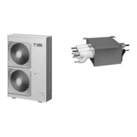
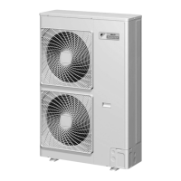
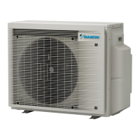
1.1 Outdoor Unit ...........................................................................................11
1.2 BP Unit ...................................................................................................12
1.3 Indoor Unit..............................................................................................13
Part 3 Printed Circuit Board Connector Wiring Diagram ........... 26
1. Outdoor Unit..........................................................................................27
1.1 RMXS112/140/160E8V1B......................................................................27
2. BP Unit..................................................................................................30
2.1 BPMKS967B2B/B3B ..............................................................................30
3. Indoor Unit.............................................................................................31
3.1 Wall Mounted Type ................................................................................31
3.2 Floor Standing Type ...............................................................................44
3.3 Floor / Ceiling Suspended Dual Type.....................................................46
3.4 Duct Connected Type.............................................................................48
3.5 Ceiling Mounted Cassette Type .............................................................50
3.6 Ceiling Mounted Built-in Type ................................................................54
3.7 Ceiling Suspended Type ........................................................................59
4. Remote Controller .................................................................................61
4.1 Wired Remote Controller........................................................................61
4.2 Wireless Remote Controller ...................................................................63
Part 4 Refrigerant Circuit ........................................................... 65
1. Refrigerant Circuit .................................................................................66
1.1 Outdoor Unit ...........................................................................................66
1.2 BP Unit ...................................................................................................68
2. Functional Parts Layout ........................................................................69
2.1 Outdoor Unit ...........................................................................................69
3. Refrigerant Flow for Each Operation Mode...........................................71
3.1 Cooling Operation ..................................................................................71
3.2 Heating Operation ..................................................................................72
3.3 Cooling Oil Return Operation .................................................................73
3.4 Heating Oil Return Operation & Defrost Operation ................................74
Part 5 Function............................................................................ 75
1. Operation Mode ....................................................................................77
2. Basic Control.........................................................................................78
2.1 Normal Operation ...................................................................................78
2.2 Compressor PI Control...........................................................................79
2.3 Electronic Expansion Valve PI Control...................................................80