www.DaikinApplied.com 9 IOM 1207-6 • TRAILBLAZER
®
MODEL AGZ CHILLERS
CAUTION
All lifting locations must be used to prevent damage to unit.
DANGER
Improper rigging, lifting or moving of a unit can result in property
damage, severe personal injury or death. Follow rigging and moving
instructions carefully. Do not stand beneath the unit while it is being
lifted or installed.
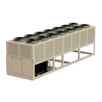
Figure 1: Required Lifting Arrangement
Unit Placement
Trailblazer
®
units - both packaged units with pump packages
and condensing units for remote evaporator congurations -
are for outdoor applications and can be mounted either on a
roof or at ground level. For roof mounted applications, install
the unit on a steel channel or I-beam frame to support the unit
above the roof. For ground level applications, install the unit on
a substantial base that will not settle. Use a one-piece concrete
slab with footings extended below the frost line. Be sure the
foundation is level within 0.5” (13 mm) over its length and
width. The foundation must be strong enough to support the
unit weight - see Dimensional Drawings for Remote Evaporator
Units beginning on page 29 or see Dimensional Drawings
for Pump Package Units beginning on page 45.
Mounting Hole Access
The inside of the base rail is open to allow access for securing
mounting bolts, etc. Mounting location dimensions are given
in Dimensional Drawings beginning on page 29 for remote
evaporator units or page 45 for pump package units.
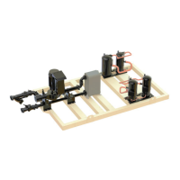
All compressor bolts, rubber grommets, and fasteners should
be left in place on the base plate as shown in Figure 2. None
of these fasteners are considered to be ‘temporary shipping
bolts.’
Figure 2: Compresssor Base Plate Mounting
Operational Spacing Requirements
Sucient clearance must be maintained between the unit
and adjacent walls or other units to allow the required unit air
ow to reach the coils. Failure to do so will result in a capacity
reduction and an increase in power consumption. No solid
obstructions are allowed above the unit at any height, see page
12 for details.
The clearance requirements shown are a general guideline
and cannot account for all scenarios. Such factors as prevailing
winds, additional equipment within the space, design outdoor
air temperature, and numerous other factors may require more
clearance than what is shown. Additional clearances may be
required under certain circumstances.
Graphs on the following pages give the minimum clearance for
dierent types of installations and also capacity reduction and
power increase if closer spacing is used. The graphs are based
on individual cases and should not be combined with other
scenarios.
CAUTION
Unit performance may be impacted if the operational
clearance is not sucient.
Service Clearance
The control panels are located on the end of the chiller and
require a minimum of four feet of clearance in front of the
panels. Compressors, lter-driers, and liquid line shuto valves
are accessible on each side or end of the unit. Do not block
access to the sides or ends of the unit with piping or conduit.
These areas must be open for service access. Minimum
service clearance is as follows:
Sides
• 4 Fan Models: Minimum of 4 feet (1.2 meters)
• 6 to 14 Fan Models: It is highly recommended to
provide a minimum of 8 feet (2.4 meters) on one side to
allow for coil replacement. Coils can be removed from
NOTE: Number of
fans and rigging
holes may vary
from this diagram.
The lifting method
will remain the
same.
 Loading...