Do you have a question about the Daikin UATYQ20ABAY1 and is the answer not in the manual?
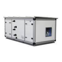
This document serves as an operation manual for Daikin Rooftop Packaged Units, providing end-users with a concise overview of the unit's control functions and user interface. It outlines how to navigate the software menu, adjust settings, and interpret various operational displays and alarms.
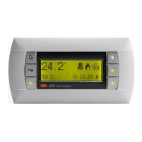
The Daikin Rooftop Packaged Unit is controlled via an LCD display with a user-friendly interface. This interface, featuring 4 rows and 20 columns with automatic backlight, allows users to interact with the unit's software menu and adjust parameters. The primary function of the unit is to provide climate control, offering modes such as cooling, heating, freecooling, and dehumidification, depending on the model and configuration. The control system manages compressors, fans (main, plug-fan, and external), electrical heaters, and other components to maintain desired indoor conditions. It also incorporates safety features, such as high and low-pressure alarm prevention and antifreeze functions. The unit supports time-based programming, allowing users to set daily and weekly operating schedules, including specific temperature setpoints for summer and winter modes.
The user interface is designed for intuitive operation using six function keys:
Upon powering on, the main mask displays the indoor temperature setpoint, unit address, current indoor temperature, and the unit's status along with the current time. Users can navigate through various sub-masks to view detailed operational information, such as:
The software menu is structured with different access levels: free, partially password-protected, and completely password-protected. End-users typically have free access to essential settings like temperature and airflow setpoint adjustments, clock settings, and time slot programming.
Setpoint Adjustment: Temperature and airflow setpoints can be adjusted from the main mask using the arrow keys and confirmed with the "Enter" key. Separate setpoints are available for summer and winter operation, as well as external air temperature compensation.
Clock and Time Slots Setting: The "Clock" menu allows users to set the current date and time. The "Time zone" menu (K2-K7 masks) enables programming daily and weekly operating schedules, including specific ON/OFF times and internal/external setpoints for both summer and winter. This feature allows for energy optimization by aligning unit operation with occupancy schedules.
Summer/Winter Changeover: The unit can be switched between summer and winter modes from the keyboard, provided the unit is OFF and this function is enabled. Automatic changeover is also supported, where the unit transitions between modes based on indoor air temperature relative to the summer and winter setpoints. It's crucial that the winter setpoint is lower than the summer setpoint to prevent alarms and unit stoppage.
Input/Output Visualization: Users can view real-time data from various sensors and components, including:
Language and Unit Data Visualization: The "Maintenance" menu allows changing the control language. It also provides access to unit-specific information such as serial number, factory testing date, tester identification, software code, version, release date, unit model, control board BIOS and boot versions, and total unit working hours, as well as working hours for individual compressors.
The manual provides a comprehensive alarm list, which is crucial for troubleshooting and maintenance. When an alarm is triggered, the red "Alarm" key illuminates, and a digital output is activated. Pressing the "Alarm" key displays the most recent alarm, and users can scroll through other active alarms. Each alarm is identified by a code (ALxx) and a description of its cause.
Alarm Reset: Alarms can be reset manually by pressing and holding the "Alarm" key for at least two seconds, provided the condition that triggered the alarm is no longer present. The manual emphasizes the importance of investigating and resolving the alarm cause before resetting to prevent damage to the unit. Some alarms reset automatically when their conditions disappear, while others require manual intervention.
Alarm History: The unit stores the last 150 alarms in its history menu. When the memory is full, the oldest alarm is overwritten by new ones. For manual reset alarms, the reset day and time are recorded in the alarm history.
Alarm Information: The alarm list includes:
Maintenance alarms (e.g., compressor or unit maintenance thresholds exceeded) must be reset from specific masks within the "Maintenance" menu and cannot be cleared using the "Alarm" key. This distinction ensures that scheduled maintenance checks are performed before these specific alarms are cleared.
| Model | UATYQ20ABAY1 |
|---|---|
| Category | Air Handlers |
| Refrigerant | R410A |
| Voltage | 220-240 V |
| Phase | 1 |
| Frequency | 50 Hz |