EasyManua.ls Logo

Daikin EKEQFCBAV3-US User Manual

Daikin EKEQFCBAV3-US
20 pages
To Next Page IconTo Next Page
Page #1 background imageLoading...
Page #1 background image
EKEQFCBAV3-US (EEV KITS)
INSTALLATION INSTRUCTIONS

Optional kit to use in combination with Daikin condensing units
with eld supplied non VRV air handler units.
Field supplied air handler units can be connected with a Daikin
condensing unit via a control box and expansion valve kit. Each
circuit or coil requires a separate control box and expansion valve
kit. This manual describes the installation of the expansion valve
kit and the installation and operation of the EKEQMCBAV3-US
control box.
The below mentioned cautions should be considered prior to
installation
Multi-module condensing units are permitted. However,
each refrigerant system cannot exceed the maximum
tonnage allowed by the applicable VRV heat pump system
type.
The automatic refrigerant charging and leak detection
function are not possible when the EKEQMCBAV3-US is
used.
The manufacturer of the outdoor unit has limited
responsibility for total performance of the system because
performance is determined by the total system. The
discharge air may uctuate depending on selected
air handler units and depending on the installation
conguration.
Connectivity to DIII-net devices only allowed with:
- Intelligent Touch Manager
This equipment is not designed for year-round cooling
applications with low indoor humidity conditions, such as
Electronic Data Processing rooms.
Only personnel that have been trained to install, adjust, service

manual should service the equipment. The manufacturer will not
be responsible for any injury or property damage arising from
improper service or service procedures. If you service this unit,
you assume responsibility for any injury or property damage
which may result. In addition, in jurisdictions that require one or

only licensed personnel should service the equipment.
Improper installation, adjustment, servicing or repair of the


without proper training may result in product damage, property
damage, personal injury or death.
WARNING
Cancer and Reproducve Harm -
www.P65Warnings.ca.gov
PROP 65 WARNING
FOR CALIFORNIA CONSUMERS
0140M00517-A
WARNING
S
AFELYD ISPOSE OF ALLP ACKING ANDT RANSPORTATIONM ATERIALS
IN ACCORDANCE WITH FEDERAL
,
STATEA ND LOCALL AWSO R
ORDINANCES
. P
ACKING MATERIALSI NCLUDING NAILS
,
METAL
,
WOODEN PARTSA ND PLASTICP ACKING ITEMSU SEDI NT RANSIT MAY
RESULT IN INJURY OR DEATHB YS UFFOCATION
.
WARNING

Upon receiving the unit, inspect it for damage from shipment.
Claims for damage, either shipping or concealed, should be
led immediately with the shipping company. Do not install this
accessory if it is determined that the integrity or safety has been
compromised by freight damage.
Check the unit model number, specications, and electrical char-
acteristics to determine if they are correct. In the event an incor-
rect unit is shipped, it must be returned to the supplier and must
NOT be installed. The manufacturer assumes no responsibility for
installation of incorrectly shipped units.

Carefully read all instructions for the installation prior to installing
product. Make sure each step or procedure is understood and
any special considerations are taken into account before starting
installation. Assemble all tools, hardware and supplies needed to
complete the installation. Some items may need to be purchased
locally. Make sure everything needed to install the product is on
hand before starting.
19001 Kermier Rd., Waller, TX 77484
www.daikincomfort.com
IOD-7042D
08/2020
© 2015 - 2016, 2020
Question and Answer IconNeed help?

Do you have a question about the Daikin EKEQFCBAV3-US and is the answer not in the manual?

Daikin EKEQFCBAV3-US Specifications

General IconGeneral
Model NumberEKEQFCBAV3-US
CategoryAir Handlers
Voltage208-230V
Phase1
Frequency60Hz
RefrigerantR-410A
Airflow1200 CFM
Cooling Capacity36000 BTU

Summary

Safety Considerations and Initial Checks

General Safety and Technician Training

Covers technician qualifications, property damage, and injury risks, including specific warnings for California consumers.

Product Inspection and Pre-Installation Steps

Outlines procedures for checking the received product for damage and preparing for installation.

Safety Information and Regulatory Compliance

Safety Symbols, Labels, and Electrical Hazards

Explains safety symbols, labels, and addresses high voltage, grounding, and general electrical safety.

Handling Precautions and Device Compliance

Covers safety clothing, use of approved devices, and adherence to national and local installation codes.

Model Identification and System Components

Component Overview and Accessory Contents

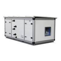
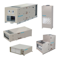
Lists system parts and details the obligatory and optional accessories included with the kit.

Installation Preparation and Capacity Information

Pre-Installation Guidelines and Refrigerant Handling

Covers piping, cleaning, and specific precautions for R410A refrigerant.

System Capacity Limits and Coil Selection Criteria

Details allowed heat exchanger capacities, connection ratios, and coil selection criteria.

Installation Notes and Site Requirements

Expansion Valve Control and Air Handler Compatibility

Discusses electronic valve control, air handler unit requirements, and capacity setting adaptor selection.

Installation Site Selection and Environmental Precautions

Defines site conditions and lists areas where the unit should not be installed.

Piping and Valve Kit Installation Procedures

Piping Connections, Material Selection, and Brazing Safety

Covers pipe connections, material specifications, and safe brazing practices.

Valve Kit Mechanical Installation Steps

Step-by-step guide for physically installing the valve kit box and components.

Field Piping and Electrical Connection Steps

Field Piping Brazing and Insulation Techniques

Instructions for preparing and brazing field piping, including safety warnings for heat and protection.

Electrical Box Wiring and Cable Management

Steps for opening the electrical box, passing the valve cable, and securing it.

Electrical Control Box Installation Guide

Control Box Mounting and Internal Wiring Instructions

Details mechanical installation of the control box and its internal wiring connections.

Conduit and Wiring Installation Procedures

Conduit Fitting Installation and Control Box Wiring

Instructions for installing conduit fittings and connecting power/control wires to the control box.

Wiring Placement and Connection Best Practices

Guidelines on wire placement to prevent noise and ensure secure, watertight connections.

Wiring Diagram and Connection Details

Terminal Board Wiring Procedure and Diagram

Step-by-step guide for connecting wires to the terminal board according to the wiring diagram.

Wire Connection Specifications and Labels

Details wire types, terminal connections, and their corresponding functions and color codes.

Detailed Wiring Specifications

Power, Signal, and Wire Gauge Specifications

Details specifications for power supply, control signals, wire gauges, and maximum cable lengths.

Refrigerant Thermistor Installation

Thermistor Cable Routing and Protection

Instructions for routing, protecting, and securing thermistor cables to prevent damage and ensure accuracy.

Thermistor Placement and Maximizing Contact

Guidance on placing thermistors correctly for accurate readings and ensuring good heat contact.

Thermistor Cable Extension and Test Operation

Extending Thermistor Cables and Pre-Test Checks

Procedure for joining thermistor cables and performing essential checks before test operation.

Test Operation and Performance Verification

Steps for verifying correct system operation after installation, including opening valves and confirming fan status.

System Settings and Control Configuration

0-10V Capacity Control System Setup

Describes setting up the 0-10V capacity control system using a field-supplied controller.

Indoor Fan Control Settings and Modes

Explains how to configure indoor fan operation modes for different system states.

Operation Signals and Troubleshooting Guide

Operation Signals and Display Status Indicators

Details the meaning of various output and input signals for system status.

Troubleshooting Common System Malfunctions

Provides steps for diagnosing and resolving common system malfunctions and error codes.

Maintenance, Disposal, and Regulatory Compliance

Maintenance Precautions and Proper Disposal Methods

Covers warnings for maintenance, especially electrical hazards, and guidelines for proper unit disposal.

Regulatory Adherence and Refrigerant Handling Guidelines

Mentions adherence to national codes and EPA regulations for refrigerants.

Related product manuals