4
• Refer to the installation manual of the outdoor unit for details
on refrigerant piping, additional refrigerant charging, and
inter-unit wiring
S
INCE
DESIGN
PRESSURE
IS
478
PSI
(3.3
A
)
OR
33
BAR
,
PIPES
OF
LARGER
WALL
THICKNESS
MAY
BE
REQUIRED
. R
EFER
TO
PARAGRAPH
“S
ELECTION
OF
PIPING
MATERIAL
”.
MP
WARNING
• Precautions for R410A
The refrigerant requires strict cautions for keeping the sys-
tem clean, dry and tight.
Clean and dry
Foreign materials (including mineral oils or moisture) should
be prevented from getting mixed into the system.
Tight
Read “Piping installation” carefully and follow these proce-
dures correctly.
Since R410A is a mixed refrigerant, the required additional
refrigerant must be charged in its liquid state. (If the refrig-
erant is in state of gas, its composition changes and the
system will not work properly).
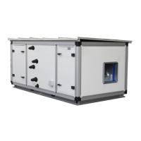
The connected air handler units must have heat exchangers
designed exclusively for R410A.
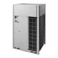
VRV IV Range Outdoor Units
The EKEQFCBAV3-US control box can be connected to VRV IV
heat pump systems only with a maximum number of 3 connect-
able control boxes to 1 system. 1 control box can be combined
with 1 EKEXV kit. In this conguration it is only allowed to connect
air handling units. The combination with VRV DX indoor units or
other types of indoor units is not allowed.
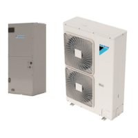
When connecting more than one EKEQFCBAV3-US to a VRV
outdoor unit, the associated EKEXV expansion valves must be
connected to a single air handling unit consisting of multiple inter-
laced circuits.
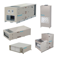
Depending on the air handler unit’s heat exchanger, a connect-
able EKEXV (expansion valve kit) must be selected to meet the
limitations specied in Table 1 and Table 2.
For maximum number of indoor units, see the outdoor unit speci-
cations.
If the total capacity of the connected indoor units exceeds the
capacity of the outdoor unit, cooling and heating performance may
drop when running the indoor units.
Refer to the section on performance characteristics in the engi-
neering manual for details.
The capacity class of the air handler unit is determined by the se-
lection of the expansion valve kit according to Table 1 and Table 2.
Depending on the heat exchanger, a connectible EKEXV (expan-
sion valve kit) must be selected to these limitations.
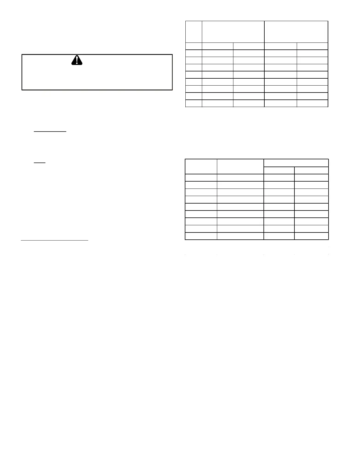
63 21500, (6.3) 26500, (7.8) 24200, (7.1) 30000, (8.8)
80 27000, (7.9) 33800, (9.9) 30500, (8.9) 38000, (11.1)
100 34000, (10.0) 42000, (12.3) 38500, (11.2) 47000, (13.8)
125 42500, (12.4) 52500, (15.4) 47500, (13.9) 59000, (17.3)
140 53000, (15.5) 60000, (17.6) 59500, (17.4) 67500, (19.8)
200 60500, (17.7) 84000, (24.6) 68000, (19.9) 94500, (27.7)
250 84500, (24.7) 105000, (30.8) 95000, (27.8) 118500, (34.7)
400 105000, (30.8) 16900, (49.5) 118500, (34.7) 187500, (55.0)
500 170000, (49.6) 210000, (61.6) 188000, (55.1) 236500, (69.3)
Allowed heat exchanger
cooling capacity Btu, (KW)
Allowed heat exchanger
heating capacity Btu (KW)
Cooling saturated suction temperature
(SST) = 43°F (6°C)
Standard Air temperature = 81°F (27°C)
DB / 66°F (19°C) WB
Extended Air temperature = 91°F
(32.7°C) DB / 82°F (27.7°C) WB
Superhea t (SH) = 9°F (5°C)
Liquid temperature = 77°F (25°C)
Heating saturated condensing
temperature (SCT) = 115°F (46°C)
Standard Air temperature = 68°F (20°C)
DB
Extended Air temperature = 32°F (0°C) DB
/ 27°F (-2.7°C) WB
Subcool (SC) = 5.4°F (3°C)
Vapor temperature = 140 °F (60°C)
Table 1
Hea t Exchanger Volume (i n
3
)
Note: The header and distributor are not included when
determining the coil volume.
Table 2
The air handler unit can be connected as a standard VRV indoor
unit. The combinations of EKEXV kits (maximum 3) are restricted
by the connection ratio limitations: 90~110%.
Additional limits exist when connecting the
EKEQFCBAV3-US control box. These can be found in the Speci-
cation Sheets of the EKEQFCBAV3-US and in this manual.
1. Selecting the expansion valve - The corresponding expan-
sion valve needs to be selected for your air handler unit. Se-
lect the expansion valve according to the above limitations.
2. When making the coil selection, the following criteria should
be used to determine the suitability of the selected coil:
a. At nominal conditions, the refrigerant velocity in the coil
tubes should exceed 1,000 feet per minute.
b. At nominal conditions, the pressure drop through the coil
should not exceed 10 psi.
c. At nominal condition, the pressure drop through the
distributor should not exceed 31 psi.
d. The hair pin size of the heat exchanger should be 3/8” or
smaller.
e. The minimum air ow should be 70% or greater than the
air ow at nominal conditions. (80-110% when operating
in the extended range, see selection guide for extended
range details)
 Loading...