Do you have a question about the Daikin RXQ12AHR and is the answer not in the manual?
Essential safety warnings for repair work and product usage, including pictograms.
Explanation of icons used in the manual to attract attention to specific information.
Details of document revisions, including version and publication date.
Lists indoor and outdoor unit model names and their corresponding series and power supply.
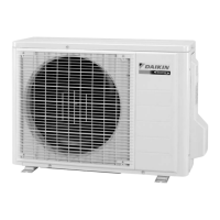
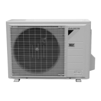
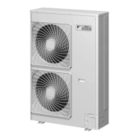
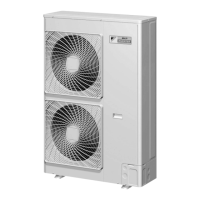
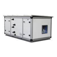
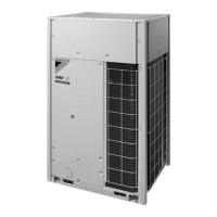
Illustrations showing the external appearance of VRV indoor and outdoor units.
Details combinations of outdoor units for VRV X Series High-COP and Standard types.
Information on the connection ratio for VRV indoor units and outdoor unit combinations.
Technical specifications for VRV X Series High-COP and Standard Type models.
Piping diagrams illustrating the refrigerant flow for outdoor and VRV indoor units.
Diagrams showing the layout of key functional components within outdoor units.
Flowcharts illustrating refrigerant flow during cooling and cooling oil return operations.
Lists indoor unit series and their corresponding wired and wireless remote controllers.
Detailed description of buttons and functions for various remote controller models.
Procedure for setting main/sub controllers for indoor units and handling errors.
Steps for setting addresses for receivers and wireless remote controllers for multi-unit systems.
Instructions for setting group numbers for centralized control using remote controllers.
Guide to accessing and navigating service settings and maintenance menus.
Overall system operation flowchart, detailing stop, standby, startup, normal, and special controls.
Explanation of abnormal shutdown and slave unit stop conditions and countermeasures.
Explanation of pre-pressure equalization and cooling startup control procedures.
Description of compressor control modes: VRTsmart, VRT, and Te fix control.
Details on high pressure, low pressure, discharge pipe, compressor body, and inverter protection controls.
Explanation of outdoor unit rotation and oil return operations for system longevity.
Description of thermostat control, airflow rate, and direction control for indoor units.
Procedures for configuring indoor unit settings using remote controllers.
Details on setting outdoor unit functions using DIP switches and BS buttons.
Guidelines for performing system test operations, including checks and procedures.
Initial verification steps and precautions for maintenance procedures.
Troubleshooting guide based on observed symptoms and their supposed causes.
Steps to troubleshoot errors and warnings displayed on wired and wireless remote controllers.
Detailed list of error codes, their descriptions, and troubleshooting steps.
Procedures for checking system components like pressure sensors and wiring.
Detailed wiring diagrams for outdoor and VRV indoor units.
| Brand | Daikin |
|---|---|
| Model | RXQ12AHR |
| Category | Air Handlers |
| Language | English |